Electro Tech is an online community (with over 170,000 members) who enjoy talking about and building electronic circuits, projects and gadgets. To participate you need to register. Registration is free. Click here to register now.
Welcome to our site! Electro Tech is an online community (with over 170,000 members) who enjoy talking about and building electronic circuits, projects and gadgets. To participate you need to register. Registration is free. Click here to register now.
I want to make an discrete inverter to replace 74HC04. And, the discrete inverter can keep the supply current drawn both static and dynamic remains the same, no matter of the state of the inverter. How can I make it? Any circuits?
CMOS logic dissipates more power as the frequency increases for two reasons. One is "shoot-through" current, and the other is due to the fact that it will always have a capacitive load that has to be charged and discharged at the switching frequency.
The shoot-thru current is caused by the fact that the pullup (Pchan) and pulldown (Nchan) transistors are on simultaneously during the transition between logic levels. This can possibly be alleviated somewhat by clever circuit design, probably at the expense of propagation delay.
The capacitor charging power cannot be eliminated. The capacitance is the sum of device output capacitance, package parasitic capacitance, wiring capacitance, and the capacitance of any devices which are being driven. The power dissipated by the logic device driving this capacitance is
P = F*C*V^2
Where F is the switching frequency, C is the aforementioned capacitance, and V is the supply voltage of the CMOS logic device.
Having explained all this, I gotta say I'm not sure this this addresses your question. :roll: Does it? What problem are you trying to solve?
A CD4069 or 74C04 inverter also works with a 5V supply and has a much lower "shoot-through" current than a 74HC04 inverter. Its penalty is that it is much slower.
74HCxx ICs have such a high supply current when their output is "halfway" that their datasheet spec's a short max switching time for them.
Maybe you could use a Schmitt-trigger inverter like a 74HC14, CD74C14 or MC14584 if you have slowly changing inputs. Their "snap action" reduces power supply current considerably. :lol:
Actually, in my design, I only need a single inverter. So, I want to use a discrete circuit (a single or 2 transistors) to make an inverter. I tried to search some sample circuits in yahoo.com, but got nothing. Could you all help on this?
Actually, in my design, I only need a single inverter. So, I want to use a discrete circuit (a single or 2 transistors) to make an inverter. I tried to search some sample circuits in yahoo.com, but got nothing. Could you all help on this?
Naaaaaah! What's a little VHF among a bit of 2MHz logic?
And yes, there are manufacturers out there that are making single-function SMT logic, the idea being to place your logic physically where you need it without having to get the wiring run to a multiple-gate chip. It's the best way to keep it small and keep the specs high.
Hey Russ,
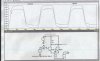
Your circuit is exactly the same as I have written on my notepad but you beat me because I had to go out. As for your 2N2369 transistors, I have some brand new ones about 40 years old! :lol:
But NOT 50 years old, that's 1955, the year the transistor was invented (and the year I was born 8) ) - surely no coincidence?. Those transistors were 1960's, well after the OC71 series, which weren't that early either. There's not going to many 1955 transistors about (if any?).
wowww OC71... it is probably the oldest one i've ever held in my hands.
not sure if i still have one but i remember black painted glass ampulas
with three long wires and a little red dot. paint would peel too easily...
OC71's were fairly expensive (actually VERY! expensive), but you could buy cheaper transistors, simply marked 'red spot' or 'white spot', I seem to remember one was an RF transistor, the other an audio transistor, but I can't remember which was which?.
I got my 1st transistor radio in about 1958 and it had transistors in metal cases with the top pinched then welded shut.
Then I got my 1st job at Philips and saw lots of cool new stuff like the 1st cassette player to play music instead of speech, and the LED "with its junction glowing red-hot". :lol:
Nigel, the transistor was discovered (not really invented) in 1948. I remember trying to make my own out of a germanium 1N34 but since I didn't know what I was doing, it didn't work. I was working for GE in 1956 and GE was making transistors then. So my transistors are 49 years old!
This site uses cookies to help personalise content, tailor your experience and to keep you logged in if you register.
By continuing to use this site, you are consenting to our use of cookies.