Electro Tech is an online community (with over 170,000 members) who enjoy talking about and building electronic circuits, projects and gadgets. To participate you need to register. Registration is free. Click here to register now.
Welcome to our site! Electro Tech is an online community (with over 170,000 members) who enjoy talking about and building electronic circuits, projects and gadgets. To participate you need to register. Registration is free. Click here to register now.
I suggest you try giving more detail?, your original request is much too vague - we need to know EXACTLY what you are trying to do!.[/quote]
I have a 9vdc squarewave signal (7Hz), I would like to get plus and minus 5-8 volts out (with descrete components). So a 16 volt squarewave out with a common ground so it swings plus 8 and minus 8 volts (or 5 volts just more that 4.5).
By EXACTLY, I meant just that, WHY do you need these specific voltages - if indeed you do?, what does it do, and what supplies are available. By simply capacitor coupling the output you will get +/-4.5V!.
What is the load on your output square wave? Do you have any power supplies available, or does this all have to be powered by the 9V square wave? If the latter, what is the impedance of the 9V square wave?
What is the load on your output square wave? Do you have any power supplies available, or does this all have to be powered by the 9V square wave? If the latter, what is the impedance of the 9V square wave?
It will be powered by a nine volt battery, the input is a 5VDC squarewave from a microcontroller. The output can be microamps, as I was going to drop a 10 meg in line with each lead. It will be used like a tens unit. I have it working now, with the 7660 and AVR 1200 for control. Looking to go to 555 and decretes if possible. But I need a plus and minus out and 15 volts of so peak to peak.
Not sure if that will work, but easy enough to build and see.
I will have a 9V square wave out of the 555, Not sure how I will have a larger square wave (over 9V) out that swings plus and minus of a common reference point. Will be nice if it is that simple.
Not sure if that will work, but easy enough to build and see.
I will have a 9V square wave out of the 555, Not sure how I will have a larger square wave (over 9V) out that swings plus and minus of a common reference point. Will be nice if it is that simple.
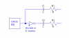
It's a standard technique called 'bridging', it provides twice the output swing of a single ended system - for car audio use a single ended 4W amplifier becomes a 16W bridged amplifier by using two anti-phase 4W amplifiers.
It's a standard technique called 'bridging', it provides twice the output swing of a single ended system - for car audio use a single ended 4W amplifier becomes a 16W bridged amplifier by using two anti-phase 4W amplifiers.
That is cool.. But would one R be my scope grounding point or the ground on the 555? It will be a square wave over 9V (say it was 14V) and I would see +7 and -7V?
Connect the ground of the scope to one R, and the probe to the other R, you should see a 14V-18V square wave - with the scope set to DC it should go above and below zero volts.
Most 10X scope probes are 10Meg input resistance. If you use one 10Meg resistor on your circuit, your scope will attenuate the signal by 50%, so you'll only see 9V p-p. If you use two 10Meg resistors, you'll only see 6V p-p. If you want to see full amplitude, measure on the other side of the resistors.
Most 10X scope probes are 10Meg input resistance. If you use one 10Meg resistor on your circuit, your scope will attenuate the signal by 50%, so you'll only see 9V p-p. If you use two 10Meg resistors, you'll only see 6V p-p. If you want to see full amplitude, measure on the other side of the resistors.
Ron H and Nigel. Thanks for the really neat circuit. You guys are great. Next time put more details in the question as not to fill up this forum so badly..
This site uses cookies to help personalise content, tailor your experience and to keep you logged in if you register.
By continuing to use this site, you are consenting to our use of cookies.

")