Continue to Site

Welcome to our site!

Electro Tech is an online community (with over 170,000 members) who enjoy talking about and building electronic circuits, projects and gadgets. To participate you need to register. Registration is free. Click here to register now.

  • Welcome to our site! Electro Tech is an online community (with over 170,000 members) who enjoy talking about and building electronic circuits, projects and gadgets. To participate you need to register. Registration is free. Click here to register now.

Help! creating 1 watt LED driver circuit...

Status
Not open for further replies.
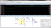
Take Note that in MikeML's last design, the Vds during CC mode is 2.4V @ 0.3A which is due to the difference between V+ and the LED String forward voltage ( plus 0.6V Vbe drop). This can be reduced is something better than a transistor was used such as a n Op Amp with suitable matching of LED string voltage and Supply difference to minimize wasted heat in MOSFET (2.4V*0.3A = 0.72 W )

Using a much smaller Current sense shunt resistor say a 50mV drop allows the V+ to be reduced almost 2.4V or raised by 0.6V and add another LED in the string. or as many as desired ( <3V+ per LED)

So you can see the most efficient solution of current regulation comes from matching the LED string to the Regulated supply voltage. If the voltage is not well regulated then this headroom or drop to the Vds must exceed the Supply variation. If the voltage is too large then some PWM method must be used to minimize excess power drop in the MOSFET switch.
 
Hi,

Usually it is hard to match the voltage to the LED(s) for good efficiency. If you can that's great, but you need to analyze the circuit very carefully. If you cant then you need a switcher. Not just any switcher however, you want a switcher that uses a controller IC and external MOSFET. This is so that you can choose the MOSFET to be overrated for the application (very low Rds). Most ready made switcher packages have a switch transistor that ends up being a tradeoff in cost for efficiency. Using an external MOSFET eliminates this contradiction and gets the efficiency up near the max theoretical. Of course low loss inductor too, low drop Schottky or go with a dual MOSFET synchronous design. This also gives you a lot more flexibility with the choice of LED voltage ratings and power supply tolerance.
 
Would it be a good idea to use joule thief circuit for 1 watt led's?
**broken link removed**
This is the common type circuit...
**broken link removed**
In this one what's the purpose of adding 1.2nf cap here? Would there be any increment in brightness of the led?
 
Hi,

Probably not a good idea as the simpler circuits like these rely on high current pulses to light the LED. Maybe if you add a Schottky diode and capacitor to the output to smooth the current down. I would definitely check it with a scope too though before using for too long.
 
With a lot of trial and error on the magnetic design and improved low Vce(Sat) transistor, it would be a great but expensive solution and in the end still only as good or bad as the battery.

You can drive the LED direct from a Lithium 3.0V CR123 which you can buy in bulk cheap online with much better storage power and stable voltage. or add wire resistance to limit the current if you were smart to buy high quality LEDs with low Vf of 2.9V.@ 330mA (0.1V/0.33A ~ 0.3 Ohm added ESR resistance.)
 
Here's an article that may be of interest to you.
 

Attachments

  • Joule Thief modern 5252F.doc
    417.5 KB · Views: 544
  • FXETVDMGS3BC3A7.LARGE.jpg
    FXETVDMGS3BC3A7.LARGE.jpg
    119.5 KB · Views: 1,008
I have found the cheapest solution to use an old laptop charger for LEDs since they are readily available and offered in common voltages like 19.2V. Many now are "universal" with adjustable regulated voltage. Unregulated supplies like this are compromised and waste more power in the series Resistor. Since the 5mm LEDs are rated typically only 65mW max the series drop R and power dissipation ought to the same or less than 1 LED .
 
on your opening post, you said 4 1watt LEDS and a 12v battery, car bat?, is that correct? and what type of 1 watt LEDs, are the mounted to an aluminum hex star?
 

Attachments

  • Untitled.png
    Untitled.png
    103 KB · Views: 296
If you want the LED's to be constant current from 12.5 to 11.5 off battery and up to 14.2V with charger, then a constant current regulator is required.
This single chip does it all with high efficiency, and dimmable over a wide range.
http://www.linear.com/product/LT3519
8399.png
 

Attachments

  • Untitled.png
    Untitled.png
    81.3 KB · Views: 289
  • LT1270A-33UH 1w.asc
    1.9 KB · Views: 140
Nice one man, the current seems very stable at 330mA. Feel like making it but out of components... Time to go shopping.
You set the current by the R3, 1.245V/4Ω=.331a A 4.3Ω 5% gives a current of ≈290mA & ≈360mW
 
Status
Not open for further replies.

Latest threads

New Articles From Microcontroller Tips

Back
Top