Electro Tech is an online community (with over 170,000 members) who enjoy talking about and building electronic circuits, projects and gadgets. To participate you need to register. Registration is free. Click here to register now.
Welcome to our site! Electro Tech is an online community (with over 170,000 members) who enjoy talking about and building electronic circuits, projects and gadgets. To participate you need to register. Registration is free. Click here to register now.
I tried to create a 38kHZ square wave with a PIC18F1330, but it did not work. I was wondering if anybody had any code or etc on how to generate one. I will post my code later.
I tried to create a 38kHZ square wave with a PIC18F1330, but it did not work. I was wondering if anybody had any code or etc on how to generate one. I will post my code later.
What would be the frequency of the interrupts? I think it would be easier just to use the PWM software to easily generate the 38kHZ wave, then I could just upload the new software with an ICSP if I wanted to include interrupts
What would be the frequency of the interrupts? I think it would be easier just to use the PWM software to easily generate the 38kHZ wave, then I could just upload the new software with an ICSP if I wanted to include interrupts
/*
 * PWM registers configuration
 * Fosc = 8000000 Hz
 * Fpwm = 37735.85 Hz (Requested : 38000 Hz)
 * Duty Cycle = 50 %
 * Resolution is 7 bits
 * Prescaler is 1
 * Ensure that your PWM pin is configured as digital output
 * see more details on http://www.micro-examples.com/
 * this source code is provided 'as is',
 * use it at your own risks
 */
PR2 = 0b00110100 ;
T2CON = 0b00000100 ;
CCPR1L = 0b00011010 ;
CCP1CON = 0b00011100 ;
Its all in assembly! I cant read assembly! I just want to know a link our something that will show how to create a PWM 38kHZ wave with a 18F1320, 18F1330, a 18F4620 or a 18F2550?
EDIT: ok Bill that will work great, this was posted right after you so i never saw it
//This project is for producing a 38kHZ wave for a infrared detecting robot


#pragma config WDT = OFF
#pragma config OSC = INTIO2
#pragma config PWRT = ON
#pragma config LVP = OFF

#include <p18f1330.h>

void main(void)
{

    // speed up the clock to 8MHz
    OSCCONbits.IRCF0=1; OSCCONbits.IRCF1=1;
    OSCCONbits.IRCF1=1;
    OSCCONbits.IRCF2=1;
    OSCCONbits.SCS0=0;
    OSCCONbits.SCS1=0;
    //18F1330 Speed clock up to 32MHz using PLL
    OSCTUNEbits.PLLEN=1;
    ADCON1 = 0; // make RA0 digital
    TRISA = 0xFE;
    while(1)
        {
        PORTA = 0xFF;
        delay_us(13);
        PORTA = 0x00;
        delay_us(13);
    }
}
It diddnt produce the 38kHZ wave, but I am thinking of just using bills submitted code with a 18F4620 for xtreme overkill
Step through the code with the debugger and MPLABSIM. You can look at the output on the logic analyizer. It will even give you the timing so you can figure out the frequency.
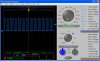
The delay functions are not that accurate. I got it going with software with nops, but what I have is all hardware. It is for a 16F628A at 4 mhz. But I know it is right. I have viewed it on my USB scope and it turns on and off my TV.
This is written in Boost C.
Code:
#include <system.h>

//Target PIC16F628A configuration word

#pragma DATA _CONFIG, _CP_OFF & _LVP_OFF & _BODEN_OFF & _MCLRE_ON & _PWRTE_ON & _WDT_OFF & _INTOSC_OSC_NOCLKOUT

//Set clock frequency
#pragma CLOCK_FREQ    4000000


// Period = CCP1Period * PreScaler * clock
//  3.2 ms = 200 * 16 *1

// Duty Cycle
//  Period * Duty% / 4 * Osc
//   3.2 * .5 = 1.6
//     1600 / 4 = 400

// 3.2 ms
/*
#define CCP1Period    199
#define    CCP1DutyCy    399
*/
// 1.6 ms
/*
#define CCP1Period    99
#define    CCP1DutyCy    199
*/
// 1.25 ms  = 800 hz
/*
#define CCP1Period    77
#define    CCP1DutyCy    155
*/
// Set Prescaler to 1:1
// 32 khz
/*
#define CCP1Period    30
#define    CCP1DutyCy    63
*/
// 38 khz

#define CCP1Period    25
#define    CCP1DutyCy    51

/*
// 40 khz
#define    CCP1Period    24
#define    CCP1DutyCy    49
*/


bit        running = 0;

unsigned char    turnon[6] = { 0x40, 4, 1, 0, 0xbc, 0xbd};

void interrupt( void )
{
    // Handle timer1 interrupt
    // Used to time the length of pulses
    if( pir1.TMR1IF )
    {
        running = 0;
        t1con.TMR1ON = 0;    // Turn TIMER1 off
        pir1.TMR1IF = 0; //clear timer 1 interrupt bit
    }
}

void xmit_pulse(short micro_pulse)
{
    static short    clock_count;
    clock_count = 65536 - micro_pulse;
    LOBYTE( tmr1l, clock_count);
    HIBYTE( tmr1h, clock_count);
    pir1.TMR1IF = 0;        // Reset overflow bit
    t1con.TMR1ON = 1;    // Turn TIMER1 on
    running = 1;

    trisb.3 = 0;
    t2con.TMR2ON = 1;
    while (running) ;        // Wait for pulse time to end
    t2con.TMR2ON = 0;
    tmr2 = 0;
    portb.3 = 0;
    trisb.3 = 1;
}

void send_on(void) {
    static char    i;
    static char    j;
    static char    t;
    static unsigned char    *ovalue;
    static unsigned char    k;

//    Send it 3 times
    for (k = 0; k < 3; k++) {
        ovalue = &turnon;
        xmit_pulse(3550);    // 4 ms header
        delay_100us(10);    // 1 ms
        delay_10us(6);        // .6 ms
        for (i = 0; i < 6; i++) {
            for (j = 8; j > 0; j--) {
                t = j - 1;
                if (test_bit(*ovalue, t)) {
//                    A one
                    xmit_pulse(512);        // 400 micro s
                    delay_100us(10);        // 1 ms
                    delay_10us(2);            // .2 ms
                }
                else {
//                    A zero
                    xmit_pulse(512);        // 400 micro s
                    delay_100us(3);            // 400 micro s
                }
            }
            ovalue++;
        }
//        End bit
        xmit_pulse(400);
        delay_ms(70);
    }
}
void main( void )
{
    static unsigned char    Low;
    static unsigned char    High;
    static unsigned int        Duty = CCP1DutyCy;
    ccp1con = 0;        // CCP Module off
    tmr2 = 0;            // Clear Timer 2
    //Configure port B
    trisb = 0x00;
    trisb.3 = 1;
    option_reg.NOT_RBPU = 0;
    //Initialize port B
    portb = 0;
    cmcon = 7; //disable comparators

    //Set timer 1
    //prescaler rate 1:1
    //Internal clock (FOSC/4)
    t1con = 00001000b;

    // Configure Capture/Compare/PWM for PWM
    // at 38khz.
    //Set timer 2 prescaler rate
    // T2CPS = 1:1
    t2con = 01001000b;
    //t2con = 0;
    pr2 = CCP1Period;
    Low = Duty & 3;
    High = Duty >> 2;
    ccpr1l = High;
    ccp1con = 00001100b;
    ccp1con.5 = Low.1;
    ccp1con.4 = Low.0;

    intcon.PEIE = 1;        // Enable peripheral interrupts
    intcon.GIE = 1;         // Enable global interrupt
    pie1.TMR1IE = 1;        // Enable Timer 1 interrupts

//    Main Loop
    send_on();
    while (1) {
    }
}
Remember that this is running at 4 mhz.
It takes one instruction to turn it on and one to turn it off.
Code:
  trisb.3 = 0;
    t2con.TMR2ON = 1;    // Turn 38khz on
    while (running) ;        // Wait for pulse time to end
    t2con.TMR2ON = 0;   //  Turn 38khz off
    tmr2 = 0;
Use the hardware..
There are commented out definitions for 40 khz and other odds and ends.
// 38 khz

#define CCP1Period    12
#define    CCP1DutyCy    25

In the main init routine

    // Configure Capture/Compare/PWM for PWM
    // at 38khz.
    //Set timer 2 prescaler rate
    // T2CPS = 1:4
    t2con = 00000001b;
    pr2 = CCP1Period;
    Low = Duty & 3;
    High = Duty >> 2;
    ccpr1l = High;
    ccp1con = 00001100b;
    ccp1con.5 = Low.1;
    ccp1con.4 = Low.0;

And to turn it on permanent like for a test
// test
    trisb.3 = 0;
    t2con.TMR2ON = 1;
    while (1) ;
It is actually much harder to get the software loop de loop correct. I have done it both ways as you saw. I would be willing to bet that my count of nops would be different on a different C compiler.
Whereas the hardware PWM will be consistent. If you notice that the off section has fewer nops because of the time doing the while calculations.
For beginner teaching, (which I understand is what you are doing), the loops may be easier to explain, but very hard to keep straight.
You really cannot use delay_us() calls because of the overhead of the call and expect easy results.
Of course, I cheated. I stuck the Parallax scope on the thing and made it right. If you call that cheating. Nearly 40 years of doing this stuff tells me you use whatever weapons you have at your disposal.
This site uses cookies to help personalise content, tailor your experience and to keep you logged in if you register.
By continuing to use this site, you are consenting to our use of cookies.

")