Continue to Site

Welcome to our site!

Electro Tech is an online community (with over 170,000 members) who enjoy talking about and building electronic circuits, projects and gadgets. To participate you need to register. Registration is free. Click here to register now.

  • Welcome to our site! Electro Tech is an online community (with over 170,000 members) who enjoy talking about and building electronic circuits, projects and gadgets. To participate you need to register. Registration is free. Click here to register now.

DS1307 RTC Problem with Unplugging Power Supply

Saeedk9574

New Member
Hi everyone,
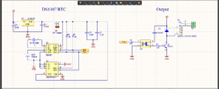
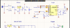
I have gotten a strange problem with my circuit. Ac you can see in schematic this a timer RTC with DS1307. In the absence of power supply, ds1307 works with coin battery.
Here I use a 12v adapter as power supply, This 12v is decreased with lm317 regulator to 3.3 for microcontroller and it is also decreased to 5v with a l7805 regulator for ds1307 RTC.
The strange problem is when I disconnect 12v adapter from wall-plug, RTC works with battery and can save time (12v adapter is connected to the board but disconnected from wall-plug )
But when I disconnect the board from 12v adapter RTC does not work and it gets reset when I connect it again to 12v.

I hope you understand what the problem is. Apparently, there is a circuit inside 12v adapter that can affect the board even though it is not connected to the outlet.


Wall-plug-----(disconnect from here)------12v adapter ------------------------------------ board =====>> it works
Wall-plug------------------------------------12v adapter---(disconnect from here)-------- board =====>> it does not works
 

Attachments

  • Screenshot (188).png
    Screenshot (188).png
    140.1 KB · Views: 81
  • Screenshot (189).png
    Screenshot (189).png
    110.9 KB · Views: 84
1st problem I can spot that may or may not be related is that your pulling up SDA/SCL to 5V yet the micro pins are NOT 5V tolerant! DS1307 will work fine with these pins pulled up to 3V3.

In fact this may be providing a path from your large 3v3 capacitor to DS1307 vcc after powerdown that is upsetting the DS1307 sequencing!

So I would normally have a diode around both linear regulators with there cathodes to +12V to provide a sane path for stray charges after powerdown.

As an aside why is there an opto-coupler in the relay drive ?
 
Last edited:
1st problem I can spot that may or may not be related is that your pulling up SDA/SCL to 5V yet the micro pins are NOT 5V tolerant! DS1307 will work fine with these pins pulled up to 3V3.

In fact this may be providing a path from your large 3v3 capacitor to DS1307 vcc after powerdown that is upsetting the DS1307 sequencing!

So I would normally have a diode around both linear regulators with there cathodes to +12V to provide a sane path for stray charges after powerdown.

As an aside why is there an opto-coupler in the relay drive ?
Based on datasheet 5v is safe for ds1307. I2c tracks between microcontroller and RTC is pull-up to 5v, however, I do not think i2c pins cause the problem.

As it is a 12v relay, I decided to separate it by optocoupler for safety.
 
If the relay is turned on at the point in time when you disconnect the 12 V, the relay current will discharge the 12 V capacitors (C1 and C?, the other 10uF one) very quickly.

However, the problem may happen when you reconnect rather than when you disconnect. You could try disconnecting at the 12 V, then disconnect the mains input, then wait for the 12 V power supply to discharge, reconnect the 12 V and then reconnect the mains.

I suggest that you use and oscilloscope to record the 12 V, the 5 V and the 3.3 V supplies during turn-on and during turn off.

You could put a diode in series with the 12 V supply to the regulators so that the coil will not discharge the capacitors quickly. You could increase the capacitor size so that the voltage falls more slowly. You could also run the 3.3 V regulator from the 5 V supply, but that would need a different type of regulator as the LM317 has a high drop-out voltage.

You could monitor the 12 V supply using the microcontroller and suspend all I2C operations below 10 or 11 V.

You definitely should change the pull ups onto the 3.3 V supply.
 
These two grounds are still tied together, the optocoupler is not isolating anything. Don’t think it is the problem, though.

View attachment 144264
The circuits he posted are just standard 'Arduino' boards available cheaply from China, hence the un-required opto-coupler, it's there as an option if needed - and does no harm regardless.

So he's not actually posted any of his own circuit, just a couple of modules he's using.
 
These two grounds are still tied together, the optocoupler is not isolating anything. Don’t think it is the problem, though.

View attachment 144264
Although it is wrong to connect these grounds together, I don't think that causes the problem. In addition, I turned of relay temporary to fix the RTC timer.
Some people supposed that I should add diodes to the both of regulators, so I did, but the problem is not fixed.
I do not really know what should I do now.
 
If the relay is turned on at the point in time when you disconnect the 12 V, the relay current will discharge the 12 V capacitors (C1 and C?, the other 10uF one) very quickly.

However, the problem may happen when you reconnect rather than when you disconnect. You could try disconnecting at the 12 V, then disconnect the mains input, then wait for the 12 V power supply to discharge, reconnect the 12 V and then reconnect the mains.

I suggest that you use and oscilloscope to record the 12 V, the 5 V and the 3.3 V supplies during turn-on and during turn off.

You could put a diode in series with the 12 V supply to the regulators so that the coil will not discharge the capacitors quickly. You could increase the capacitor size so that the voltage falls more slowly. You could also run the 3.3 V regulator from the 5 V supply, but that would need a different type of regulator as the LM317 has a high drop-out voltage.

You could monitor the 12 V supply using the microcontroller and suspend all I2C operations below 10 or 11 V.

You definitely should change the pull ups onto the 3.3 V supply.
When I disconnect 12v power supply, MCU is tuned off so relay is turned off as well, and that's Ok. I just want DS1307 RTC does not loose the track off time and it must work with the battery in the absence of 12v.
Here the strange issue is when I disconnect the board from 12v it does not work, but when I disconnect 12v power supply from outlet while it is connected to the board, RTC works with battery.

Unfortunately, I do not have oscilloscope to check this. I have added diodes to the both regulators and I also changed I2c pullup pin from 5v to 3.3v. But the problem wan not solved
 

Latest threads

New Articles From Microcontroller Tips

Back
Top