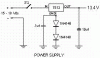
If you can't get a National Semiconductor LM1117, then maybe the NCP1117 is a copy-cat that is sold over where you are. Here is the datasheet for the LM1117:
**broken link removed**
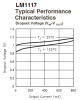
Here is its typical (some will have a higher or lower voltage) dropout voltage:
**broken link removed**
Here is its typical (some will have a higher or lower voltage) dropout voltage:
")