After what feels like forever I finally finished a basic RS485 Master/Slave network controller. The bus is a half duplex, asynchronous 2 wire bus, making use of twisted pair wire medium. The current design allows for a maximum of 8 slave network nodes.
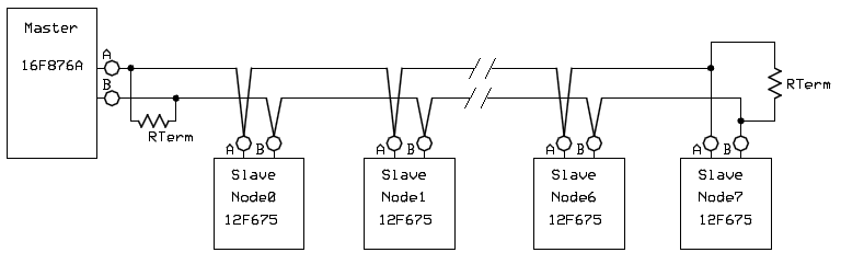
For the master I used the 28 pin 16F876A PIC. I kept the design to a maximum of 8 network nodes, because all the commands and status feedbacks to/from the slave nodes will be done via hardwired switches (for commands to the slaves) and LED’s (for status indications from the slaves). I used all eight bits on PORTC to drive status LED’s and all the bits on PORTB are wired to switches that will be used to command the respective nodes. The next design revision will have the commands and status feedback signals multiplexed, but that’s for another time.
I initially wanted to make use of the USART features in most PIC’s, BUT because I only planned on using a two wire bus system, I had to let go of the full duplex USART function. (A full duplex system will in any case require two RS485 line drivers). Instead I wrote (well, I borrowed code from ) or rather modified Nigel’s code to my needs. I had to change the way RS232 normally works (i.e. having a “space” - logic 0) to start the Rx/Tx process. Normally, if RS232 is idle, the bus is kept at a “mark” level (Logic 1). This will cause problems when all slave nodes are driving the bus high, and the master wants to transmit logic 0. Hence the need to change the start and stop bits from logic 0 to logic 1. Now, in idle state, nothing is transmitted on the bus. The receiving process now only starts when a logic level “1” is received on the bus.
The master starts by addressing Node0 first. The status of Node1 switch is merged into the transmitting register with the node number. This register is then transmitted onto the RS485 bus. Node0 should be the only slave node on the bus to reply. Once the master receives the reply back from Node0, it then increments the Node Number count, and Node1 becomes the next target. This process repeats up to Node8, where the node numbers are reset to zero, and the whole process repeats over and over.
I used the first three bits of the byte to store the node number in. I use the very last bit of the byte to store the command that will be issued to the respective node. If the master requires the node to switch on it’s output device (i.e. relay, LED etc.) the logic level of bit<7> will be high, and visa versa for switching off the device.
The slave node is built around the 8 pin 12F675 PIC. One I/O point is used for the command signal, received from the master and one I/O pin is used as status feedback back to the master. When the node receives the full byte, it goes through a decoding sequence to make sure that the address received in the byte identifies the current node. If the received node address is not the same as the pre-programmed address in the slave node, that node will not reply any data back onto the bus, and will simply keep listening until the next round of transmitted bus data comes around.
If however, the address does match, the slave node will then reply to the master the node’s address again, and the state of the node’s input switch. This switch can be a direct mechanical link to the output device (i.e. a contact on a relay) or it can be a secondary feedback condition, having no relation to the output device. A slave node will only send data back to the master if the slave node was polled by the master. Any change in the slave node’s switch status will not interrupt the bus to then transmit the change of state.
The bus communication protocol runs basically at 9600 BAUD. That’s about 100us for each bit in the byte to be sent/received. It takes a total time of about 1ms to transmit/receive one full byte, with one start and one stop bit. At this rate, each node will be addressed around 63 times per second (8 nodes). This refresh rate should be enough to pick up any state changes in any slave node switches to give a real time view.
I include schematic drawings of the maste and the slave node, as well as the asm source code files for the master and the 8 nodes. All the slave nodes source code files are basically the same with the exception of the Node Number address permanently programmed into each slave node.
Hope this may be of some use to somebody.
Regards
")
