Continue to Site

Welcome to our site!

Electro Tech is an online community (with over 170,000 members) who enjoy talking about and building electronic circuits, projects and gadgets. To participate you need to register. Registration is free. Click here to register now.

  • Welcome to our site! Electro Tech is an online community (with over 170,000 members) who enjoy talking about and building electronic circuits, projects and gadgets. To participate you need to register. Registration is free. Click here to register now.

Electromagnet Door Lock

Status
Not open for further replies.

jeyes56

Member
Hi guys,

I'm planning to make an door that is locked by an electromagnet.

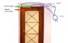
to do this, i will need a magnet attached to the door, and a electromagnet attached to the wall,

if the circuit is closed, the electromagnet will create magnetism and will pull the magnet on the door so that nobody can open the door,

i would like to know how to make an electromagnet and calculate its force exerted.
what are the materials needed,

i searched in google but what i found is just a simple electromagnet, not suitable for my project or do not have enough force exerted,


also, if you have any idea or better one regarding this topic, please suggest it to me, thanks.
 

Attachments

  • doors.jpg
    doors.jpg
    62.8 KB · Views: 2,229
Last edited:
It would need a LOT of power to lock the door using just an electromagnet and a keeper (magnet, or ferromagnetic material such as steel) as you propose, and the power would have to be continuous while the door was in the locked state. Better to use an electromagnet pulsed briefly to actuate/release a mechanical lock.
 
The amount of power that that electro-magnet is going to suck up is insane, and it's not a sure fire thing either. If someone is strong enough, they could just push the door open. I agree with alec_t, use the electro-magnet to activate a sturdier mechanical lock.
 
Also consider that in the event of a power failure, the door will be unlocked.

There are electromagnet devices for holding doors open, the idea is that when the power goes off the door is closed by a spring door closing mechanism.
These door "hold opens" are used for fire and smoke doors, so that when the fire detection system detects smoke or flames, the supply to the electromagnet is cut and the door closes preventing the spread of fire/smoke. The door can still be opened to allow access or exit as required, but the spring holds the door shut when the person has passed through the door.

JimB

On Edit:

I have just been googling and found this:
https://www.safelincs.co.uk/geofire/?gclid=CMWYldnKwKwCFUtC4Qodhh5PrA
Loads of the things!

There is no reference on their website to the power/current required to operate these things, but if you really want to electrically hold a door closed, try one of these.
 
Last edited:
There are off the shelf products for doing this, it may work well to reverse engineer them.

We use them here at work all over the place, and even myself at 250lbs can not force the door open.

**broken link removed**

**broken link removed**

**broken link removed**
 
Efficiency is all about the design of the magnet.

The above are deigned with an open W former so when the door plate is in contact it will create a closed loop of magnetic flux and this is much stronger then the magnet alone, and very little holding current is needed.
 
Yeah, we have used them at work. They also come in 12 and 24 VDC flavors making emergency back up power convenient. They work fine and last a long time, hell, no moving parts.

Making your own would likely involve patience and a mile or two (several Kilometers) of magnet wire.

Ron
 
I work in Custom Electronics assembly factory where within the same building there is another company that makes the locks DJDAudio's posted pictures of as their flagship product.
To start, You will want the magnet mounted to the wall, and a steel plate mounted to your door.
And these locks do not require as much power as you think. A 9V batter would power one of them. Second, if they're wired into a standard 120vAC supply, it's highly unlikely that anyone could just push to the door open, unless a person is capable of exerting 600lbs to 2,500lbs of force upon the door, however like it was stated these locks will fail if the power goes out. The electromagnet is made from 27awg - 17awg magnet wire (depending on the desired power of the magnet and the size limitations) The core is made from steel/ferrite "E" shaped lamination welded together. The magnet is then placed into the laminations and potted with epoxy.
I hope this was helpful.
 
Bluephoenix92 said:
600lbs to 2,500lb
In the easier sense all you need is a 10-1 leverage ratio and 60lbs of force, easy enough with a crowbar.. 2,500 is a little more difficult but still easier than getting through a steel framed door with a good dead bolt. Again there's the power problem, Wikipedia throws out a number (without refrence) of 3 watts, so all you need is power cut for a long enough period of time with no backup power. Low on security. I've personally never seen these to keep doors closed, but I see them in schools to keep doors open, when power (or an alarm) is triggered the doors shut from lack of power.

I imagine they're all low voltage powered, an open W core like that would be a shock hazard without a ballasts.
 
Last edited:
While a deadbolt is always going to be a better option for various and obvious reasons for keeping people out, the magnetic lock is more for keeping select people out, such as the small entrance that houses the ATM in some banks, where the bank wishes to restrict access to only those with ATM cards that can unlock the door via a card reader. And they're usually not very high voltage. also, usually the magnet wire is coated with what they call "heavy" insulation, as in it's Polyamide coating is twice the usual thickness, so unless there's a hole in the insulation, the core wouldn't be in direct contact with the wire, and thus not a shock hazard.
 
Thank you for response guys,

to summarize all,

to make an electromagnet, i need around 17-27AWG magnetic wire to coil to an E shaped (is it "steel-ferrite" or i can choose from steel and ferrite?) and a 12VDC source with 3Amp current, or a higher current would be better right? i should add an resistor with reasonable power rating to increase the current rating,, i just need to calculate how much turn i need and to calculate its force exerted. And an additional steel plate to attract by the electro-magnet.

wire gauge = from 17 up to 27 Awg
Voltage=12vdc
Current=3A
# turns =?
Force=?

assuming that there's no power interruption.

Im planning to integrate this with RFID Reader so that only selected people with RFID card can pass through that door.
 
Last edited:
To summarize--Yes you need that magnet wire, and the Lamination is an alloy of steel and ferrite. That is used over standard steel because this alloy doesnt retain as much magnetism once the magnet is shut off. (think of the trick of dragging a nail across a magnet to magnetize the nail. this Ferrite & steel alloy doesnt retain the magentism.) But for a home project, any steel alloy with a relatively high content of iron will suffice. As for a power supply, All the door lock magnets I've played with never needed any resistors; I was able to hook them up to standard alkalai batteries (9v, and 1.5v), and any DC step-down transformer from 3V to 12v (I never had a 24V step-down transformer laying around to try 24v.) Most of them will run on as little as .5a at 12v. And yes you just need to calculate turns, where the larger the wire, the less turns, where the 27awg I believe is a couple hundred turns or so for a decent magnet. and the steel plate the magnet adheres to that actually lockst the door is usually around 1" (25mm) thick, at least as long as the magnet, and mounted so it the magnet makes full contact to the steel plate.
And the RFID reader is nice touch if I may say so, and easily integrated into this circuit, although I am unfamiliar with the exact wiring of the magnet with an unlocking mechanism, so someone with a greater knowledge than I should probably be able to tell you how to wire your reader into it.
I hope all of this was helpful to you. and good luck with it.
 
The key word in most of this how to discussion is "lamination" and while not a card holding member of the Wikipedia they do have some interesting material that can be found here. They show some E design cores and explain some of the logic behind them. You may find that useful. Since this is at present along the lines of a science project you may want to think about finding an old transformer and applying a little hacking surgery. That would at least get you some already fabricated laminations. The hacksaw may become your new best friend. :)

That plus the suggestions of Bluphoenix92 should help get you going.

Ron
 
"you may want to think about finding an old transformer and applying a little hacking surgery. That would at least get you some already fabricated laminations. The hacksaw may become your new best friend. :) "

I completely forgot about the transformers--Ron is very right, the laminations from the transformers are the same thing, only welded together to make a solid core, though I'm sure a little creativity can make it work just as well if you lack a Tig Welder. Just find a bunch of old transformers they dont have to work, and just take the laminations inside. You can use a hacksaw, or if you're lucky enough to have a bandsaw, those work well too. (remember safetly glasses)
Thanks Ron.
 
When I was a kid, I used to scrap transformers for the copper. The laminations usually aren't welded, but I had one huge transformer, not from a TV, that was. A hammer and a chisel usually worked to remove the laminations. Unwinding the wire on a drill bit core was the fun part.
 
thank you for reply guys,

do you mean that i need to have an old transformer, remove the coil in it, and cut some part of the lamination using a hacksaw or a bandsaw?

after that i would coil a magnetic wire on the middle to the E shaped core around 100 turns or more? to be power with 12VDC

do you think the Lamination of 2AMP transformer from 220V to 12V is just fine to make this project? or i need a bigger or longer legs?
 

Attachments

  • lamination.jpg
    lamination.jpg
    8.5 KB · Views: 468
Before you get medieval on your transformer with hacksaw and angle grinder, remember that most transformer cores are made of interleaved E and I sections and with care they can be dismantled without much force, (Except to remove the first two or three E sections).

JimB
 
with care they can be dismantled without much force, (Except to remove the first two or three E sections)
JimB should have added "If you're lucky". Be aware that better quality transformers often have their laminations vacuum-impregnated with lacquer, which effectively welds them into a single block.:(
 
Status
Not open for further replies.

New Articles From Microcontroller Tips

Back
Top