Continue to Site

Welcome to our site!

Electro Tech is an online community (with over 170,000 members) who enjoy talking about and building electronic circuits, projects and gadgets. To participate you need to register. Registration is free. Click here to register now.

  • Welcome to our site! Electro Tech is an online community (with over 170,000 members) who enjoy talking about and building electronic circuits, projects and gadgets. To participate you need to register. Registration is free. Click here to register now.

Does PIC16PRO40 work well with USB to parallel converter. Software=Nigels WinPicProg

Status
Not open for further replies.

pkshima

Member
Hi,

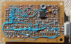
About a year back I built the PIC16PRO40 (https://www.electro-tech-online.com/custompdfs/2007/05/p16pro40.pdf) for use with my old computer which has a parallel port. So no issues.

Now I have a laptop that doesnt have a parallel port (nor a serial port). Only USB, firefire etc.

So I am unable to use my programmer with my laptop. I dont want to spend time and money in building/buying a new programmer so I am thinking of buying a USB to parallel port converter.

My problem is that I doubt if there could be issues in that approach. The software I use is WinPicProg.

Perhaps this question has been asked and answered by someone somewhere. I just failed to locate.

I struggled a lot to get my programmer to work so dont want to discard it now.

Thanks in advance for your opinions and suggestion.
 
I would say not?, it's certainly not very likely to work.

I would suggest building an ICD2 clone like the Inchworm, the curretrn versions are serial only, but will work fine with a USB/Serial converter (as it's a 'real' serial port programmer - unlike the JDM type). But I believe there's a full USB Inchworm in the planning stages?.
 
Actually the Full USB Inchworm is an upgrade to the new Inchworm+
It works and is pretty neat but the PCB is currently handwired (schematic on my site) UNICORN.

I split the design to keep Inchworm affordable and the Unicorn an option. This also allows Unicorn to be used as a project (LCD, RS485/233, keypad)

USB does not change what chips are programmed or debugged, it's just faster.

I'll be posting the more info on Unicorn soon.

PS even the Inchworm (or any ICD2 clone) can be very fussy about the RS232 port. I recommend the PL2303 USB/RS232 devices if you can find them. (Tiger direct sells em)
 
thanks for the replies.

I am quite reluctant to moving to a new programmer because

1) I have been struggling with just burning things onto a pic than actually developing for the pic which is my real goal.
2) moving to a new programmer like 'usb inchworm' will mean importing it which implies more money and more time.
3) will have to discard the programmer i built and struggled so much with.

Anyways. Nigel, why do you think the usb-->parallel converter wont work out.
Is it the software or the hardware issues ? how about 'a pciexpress card' to give out a parallel port ?
 
The way parallel port programmers work is by toggling specific pins high and low, in real time, to create a controlled syncronous serial port - under DOS or 16 bit Windows you could do this directly, and with a decent degree of precision. But 32 bit Windows (NT based) prevents direct hardware access, for good sound security reasons, so you need to use a port driver in order to access the ports - this adds an extra layer, beyond the programmer softwares control.

Now if you add a USB/Parallel converter you are adding multiple extra stages, with a slow interface in between - USB is only fast when sending multiple bytes, for single bytes it's really VERY slow - and we're talking single bits, never mind bytes!.

Circuits are freely available for ICD2 clones, as is the Inchworms, you copuld always build your own clone from scratch, no need to order a complete kit or even PCB - but you would need to design your own PCB layout.
 
Thanks Nigel.

I am wondering then how do the ICD2 clones work when connected via USB. Is the programming method used different ?

How about PCMCIA/pciexpress based parallel port expansion card. That should be fast enough to simulate a conventional parallel port.

Is it possible to build a pic device that talks to the computer using RS232/USB/ or USB->RS232 converter, takes the program a chunk at a time or the whole at once and then uses the pic16pro40 to burn the program onto the target pic ? Ahh... that will need new software right ?

I m starting to fall for the MPLAB compatibility of the ICD2 clones. But building an ICD2 clone will just start off a new project for me before I can build my real project(s). and looks like a clone cant be build on a general purpose PCB meaning getting dirty with PCB process bla bla bla :(
 
pkshima said:
Thanks Nigel.

I am wondering then how do the ICD2 clones work when connected via USB. Is the programming method used different ?
Quite simply, there's no form of parallel port involved, virtual or otherwise! They show up as a particular type of USB device, and the software is written specifically to interface with them - all the hardware is designed for this type of interface, not as some sort of a hack-job combining USB with some form of parallel port programmer.

For a USB-parallel adapter to work, the software would have to be capable of communicating with the virtual parallel port - this may not be the same as accessing a "real" parallel port, and so software written for "real" ports may not work with these adapters.

How about PCMCIA/pciexpress based parallel port expansion card. That should be fast enough to simulate a conventional parallel port.
it should certainly be fast enough, but it's still not going to do you any good unless the software is able to interface with it.

Is it possible to build a pic device that talks to the computer using RS232/USB/ or USB->RS232 converter, takes the program a chunk at a time or the whole at once and then uses the pic16pro40 to burn the program onto the target pic ? Ahh... that will need new software right ?
Uh, yes, of course it would take new software - it raises the question that if you're willing to make this fancy adapter, and write new software, why bother using the pic16pro40 at all - it would be less work to just build a suitable USB/RS232 programmer in the first place because you would be working from an existing design!
 
pkshima said:
Thanks Nigel.

I am wondering then how do the ICD2 clones work when connected via USB. Is the programming method used different ?

The ICD2 has a PIC on board, it's that PIC that does the actual programming (which gives you MUCH greater accuracy than a PC) - all the PC does is send the data to be programmed to that PIC via standard RS232. The PIC then generates the required syncronous connection to the target device, and programs the data to it.

As it's a standard RS232, and there's no speed or timing problems (that's all down to the PIC), a USB/Serial converter should work fine.

How about PCMCIA/pciexpress based parallel port expansion card. That should be fast enough to simulate a conventional parallel port.

It might be, but it would probably require different software to drive it?.

Is it possible to build a pic device that talks to the computer using RS232/USB/ or USB->RS232 converter, takes the program a chunk at a time or the whole at once and then uses the pic16pro40 to burn the program onto the target pic ? Ahh... that will need new software right ?

Yes to both, but you've just described something that sounds very much like an ICD2.

I m starting to fall for the MPLAB compatibility of the ICD2 clones. But building an ICD2 clone will just start off a new project for me before I can build my real project(s). and looks like a clone cant be build on a general purpose PCB meaning getting dirty with PCB process bla bla bla :(

No absolute need to use a PCB, in fact most of the clones start their life without a PCB - once the circuit is proved, then they design the PCB.
 
I built the first Inchworm with point to point soldering on a perfboard. Much like the one in the photo below (not mine)

On a sidenote if you're interested in microcontrollers you're going to have to do some point to point sometime... It's a pretty simple project actually.

**broken link removed**
 
I built my Serial ICD2 clone using point-to-point wiring too...


<added> the other side

icd2-clone-back-png.12685
 
Last edited:
Oh come on, don't be shy, show the other side!!
 
WoW Mike !!!

how come your board looks less complicated than the inchworm etc...
is it a different design or is it just my eyes ?

Could you please share the schematic .....

love u lots ;)
 
Mikes is based on the Lothar Stolz design just like mine. Details can be found here **broken link removed**
That design requires a 15V DC supply. Mine is 7.5V or can be target 5V powered. Using the 16F876 works but can never be upgraded to the very fast 18F4550 USB version.
PS some builders put parts under the ICs to save PCB space.
**broken link removed**
 
Last edited:
wow this guy has a usb version too. but uses all smd components which solves the biggest problem of pcb fabrication for me (drilling) but adds new problems too like if i can mix normal components with smd ones etc.

I also looked at blueroomelectronics unicorn. but I beleive it has to be used as an attachment to the inchworm+ which means 2 circuits lying around.

So here is what I think I should do. I will build the inchworm+ on a breadboard and use it with a usb-->serial cable. breadboard will save me the hasle of pcb fabrication and will also be cheaper (less than USD $2) so i wont mind using it as a pcb.

When someone shares a simple and straightforward design for USB based programer, i will either buy it or build it on a real pcb.
 
Last edited:
I've attached a picture of the back side of the my Serial ICD2 Clone (below) for those who wanted to see it. What do you think guys?

Bill is correct -- mine is based on the Stolz design with slight modifications (I added VDD switching circuitry which is supported within MPLAB). The ADC network resistors are located under the 16F876A in the open area of the machined pin socket and same for the .1-uf mono' caps located under the MAX232A. I did it this way for a compact design.

It fired up for me first time but I should mention that I've been wiring up prototype boards using that #30 Kynar wire-wrap wire for several years now.

I was thinking about designing a very compact PCB with a 28-pin footprint inside of a 40-pin footprint that would allow using either an '876A or an '877A but decided to concentrate on a compact Serial/USB (through hole) version PCB instead (coming soon, grin).

Mike
 

Attachments

  • ICD2 Clone Back.PNG
    ICD2 Clone Back.PNG
    691.9 KB · Views: 1,737
Last edited:
Thanks a lot guys for all the help !!!

and sorry for a lot of questions below ;)

Bill, I see that for the inchworm+ in the parts list, there are carbon resistors as well as metal film resistors. I am a software guy so no idea what difference it makes. Can I just use carbon resistors everywhere ?

Mike, I have done point to point some times but isnt it very inconvenient when taking insulation off short wires before soldering ?

Lothar has a USB design too but uses all SMD parts. Would it matter much if I just use regular parts in that design ? except for the FTDI chip ofcourse as it might not be available in regular (DIP ?) package.

Finally, does there exist a pic18f4550 based pic programmer that is shorter than unicorn plus inchworm+ ?
 
Last edited:
pkshima said:
Mike, I have done point to point some times but isnt it very inconvenient when taking insulation off short wires before soldering ?
It's only inconvenient in that you need to spend $10 for that stupid Radio Shack Wire-Wrap tool just to get the Kynar wire-stripper that comes with it (grin). Using the little stripper tool is a breeze and it doesn't nick the wire. It's really the only viable way I can think of to strip Kynar wire...
 
pkshima said:
Finally, does there exist a pic18f4550 based pic programmer that is shorter than unicorn plus inchworm+ ?
There are several popular USB ICD2 clone designs floating around. Some of them are much smaller than Bill's boards coupled together. Bill may be working on a "straight" USB ICD2 clone design without those extra features that are on the current board "set". There are also a couple nice USB ICD2 clones on eBay.

I'm also currently laying out a simple compact PCB for a Serial/USB ICD2 clone. The design will allow you to simply install a 28-pin '876A or a 40-pin 877A for use as a Serial ICD2, or install an '877A and a '4550 for use as a Serial/USB ICD2.
 
pkshima said:
Lothar has a USB design too but uses all SMD parts. Would it matter much if I just use regular parts in that design ? except for the FTDI chip ofcourse as it might not be available in regular (DIP ?) package.
Lothar's USB design is not a "high speed" design. That is, it doesn't have the inter-chip parallel interface of the 877A/4550 design and so it's very slow, just like a Serial ICD2, when using it in Debug mode. He simply added a USB-to-Serial chip and a VPP generator onto that design in place of the MAX232 level convertor.

Now if all you really want is a programmer with a USB interface and you don't care about the speed when using it as a debugger then you could probably do that a number of different ways. For example, I could remove the MAX232A on my home-made Serial ICD2 and install a connector for the $20 FTDI USB-to-Serial adapter cable shown below. But keep in mind that my Serial ICD2 clone uses a 15 volt external brick power supply.

Still, if you think about it, there's no reason why you couldn't modify an Inchworm similarly. Simply powering the Inchworm from the USB port and leaving the MAX232 on board to provide the 13 volt VPP voltage (but not using the MAX232 interface circuitry since the FTDI cable is TTL).

**broken link removed**
So Bill, how about another Inchworm modification (grin). A six pin header for that TTL232R adapter cable and jumpers to select the TTL232R or the MAX232 interface (grin). Seriously, this could be a simple cost effective modification; a 6 pin header and two 3 pin headers for jumpers. The end user would purchase the TTL232R adapter from Mouser if he/she needs it.
 
Last edited:
Status
Not open for further replies.

New Articles From Microcontroller Tips

Back
Top