evandude
New Member
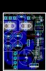
I just have a few questions. the designer of this circuit said that he went from about 60% efficiency to over 90% efficiency just by moving some wires around, and tweaking some component values. now, the values I am using are his "tweaked" values, but I'm trying to improve on the layout in any way I can. This is my current design. Anyone see any glaring issues that I should change in the layout to possibly get better efficiency?
(ignore the bottom capacitor overlapping things, the one I'm actually using is the same size as the rest of them, i just used that model in the layout because of the wider lead spacing to clear the trace going underneath)
Other than that, I just have a few questions. How much power is it OK to dissipate in a TO-220 packaged device without a heatsink? The DC-DC has a schottky diode that has a maximum forward drop of 0.5v at 20 amps I believe, and I am running both diodes in one package in parallel, usually at a few amps... so the diode drop should be even lower than that. In other words, the maximum power dissipation will be a few watts. So far the diode hasn't warmed up enough to be noticeable to the touch, but I also haven't really been pushing the current output very hard. Can anyone point me to some sort of quick estimate of what size/shape of heatsink you should use for a given wattage?
I am currently going on the "when it gets so hot it almost blows up, then i'll upgrade the heatsink" plan... but knowing a particular size I should aim for so i can take care of it once and for all would be nice. thanks...