devonsc said:Thanks for "saving" me. Thanks a lot. But I tried simulating the boost DC/DC converter without the zener diode and I couldnt obtain a constant or steady output. Is this simply because of my wrong selection of capacitor and inductor? Mind to give some hints on how should I determine the capacitor as well as the inductor value?
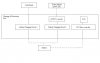
Did you simulate the circuit as shown above?, you don't have any control electronics - so there's no feedback. I'm also VERY dubious about the value of simulations, they rarely seem to work as the real world does.