Continue to Site

Welcome to our site!

Electro Tech is an online community (with over 170,000 members) who enjoy talking about and building electronic circuits, projects and gadgets. To participate you need to register. Registration is free. Click here to register now.

  • Welcome to our site! Electro Tech is an online community (with over 170,000 members) who enjoy talking about and building electronic circuits, projects and gadgets. To participate you need to register. Registration is free. Click here to register now.

Countdown Timer Question

Status
Not open for further replies.

cne

New Member
Hello,

I recently built the following project,
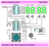
PIC Countdown Timer
And I am happy with the operation, but there are some things I want to add/change:
First of all- Instead of a start/reset switch, a start/pause, and a separate reset switch (the timer does not currently pause)
Second of all- (if possible) instead of saying 04:00, just 4:00 (blank the minute 10's if not used)

I just recently started out with PIC's, so I am not very confident in the coding aspect.
 
First of all- Instead of a start/reset switch, a start/pause, and a separate reset switch (the timer does not currently pause)
There are no spare pins on the F84 PIC to add another switch input, though if you are using the F628, you could reconfigure the MCLR pin as another input. Other wise you'll need to get fancy by using some sort of multiplexing scheme such as using the RB0-3 as the row scanning outputs. That wouldn't be too hard since they are already scanning the digit select sequence for the multiplexed LED display.

Second of all- (if possible) instead of saying 04:00, just 4:00 (blank the minute 10's if not used)
There are a couple of ways of doing that since they use the 4543 display driver:
One way is to output a nibble between 0xA and 0xF on the lower 4bits of portA as this will cause the 4543 to give a "blank" digit output.
Another way is to simply not turn on TR4 during it's normal "On Time" in the multiplex cycle when there is a zero nibble on the lower 4bits of portA.
 
First we'll try blanking that leading digit. When that is working, you can try adding the extra button which will be a little more complicated.
Try the following untested code modification (Changes in bold) of the interrupt routine from cntdwn3-628-PNP.asm

Code:
;-------------------------------------------------------------------------;
;   This is the interrupt routine that is jumped to when TMR0 overflows   ;
;                           (every 4.096 msec)                            ;
;-------------------------------------------------------------------------;

INTERRUPT   MOVWF W_TEMP        ; save W
            SWAPF STATUS,W        ; save status
            MOVWF STATUS_TEMP        ; without changing flags
;           CLRWDT            ; Clear Watchdog timer
            INCF DIGCTR,F        ; next digit #
            MOVF DIGCTR,W        ; get it into W
            ANDLW B'00000011'        ; mask off 2 lowest bits
            MOVWF DIGIT            ; save it for later
            
[B]            btfss DIGIT,0        ; These 4 lines check for a 3 in DIGIT
            goto NOT_MIN10_DIGIT
            btfss DIGIT,1
            goto NOT_MIN10_DIGIT
            movlw H'0A'            ; Make the 4543 display a blank
            goto OUTPUT_BCD        
[/B]
NOT_MIN10_DIGIT
            ADDLW H'40'            ; point at register to display
            MOVWF FSR            ; use as pointer
            MOVF INDF,W            ; get value of reg pointed to into W
OUTPUT_BCD  MOVWF PORTA            ; output to CD4543
            MOVF PORTB,W        ; read PORTB bits
            ANDLW B'00110000'        ; mask bit 4 & 5
            MOVWF TEMP            ; save it for later
            MOVF DIGIT,W        ; recall digit #
         CALL BITPAT            ; get bit pattern
            XORWF TEMP,W        ; exclusive OR with TEMP
            MOVWF PORTB            ; select transistor
            DECFSZ INTCNT,F        ; finished 1 sec?
            GOTO RESTORE        ; not yet, return and enable inter.
            CALL EVERYSEC        ; go to every second routine
            MOVLW D'244'        ; reset INTCNT to normal value
            MOVWF INTCNT        ; 
            DECFSZ FUDGE,F        ; time for fudge?
            GOTO RESTORE        ; not yet, continue on
            MOVLW H'06'            ; reset FUDGE to 6
            MOVWF FUDGE            ; 
            INCF INTCNT,F        ; INTCNT to 245
RESTORE     SWAPF STATUS_TEMP,W        ; get original status back
            MOVWF STATUS        ; into status register
            SWAPF STATUS_TEMP,F        ; old no flags trick again
            SWAPF STATUS_TEMP,W        ; to restore W
            BCF INTCON,T0IF        ; clear the TMR0 interrupt flag
            RETFIE            ; finished
 
Last edited:
Thank you for your help.
I just have one question; How do you convert the edited asm code into a hex file for programming?
 
You can use MPLAB which has MPASM (The assembler), a nice IDE, and a simulator for working with PIC code. It's a free download from **broken link removed**.
 
I am building the timer for a scoreboard, so the digits are going to be large. I have built them, and they consist of 5 red LED's in series with a 220R resistor. The supply voltage for the display is 18v.

When I hooked them up to the timer, they all interfered with one another. I know the circuit was right because it worked with the small digits, and the big digits were correctly wired.

I went back to the small digits, but found out that if you apply over 5 volts to the display, it somehow interferes with the rest of the circuit.

This is funny because in the design it says the digits use 8v.
 

Attachments

  • digits large.jpg
    digits large.jpg
    36.1 KB · Views: 322
That single transistor high side driver circuit is not good. You'll need something like this to keep the PIC from seeing more than 5v on its I/O pin;

hi-side-png.38917


You could also use one of the 500-ma high side (sourcing) driver ICs like the Allegro UDN2981 or the Micrel MIC5891 but they're a bit expensive.

Regards, Mike
 

Attachments

  • Hi Side.PNG
    Hi Side.PNG
    5.5 KB · Views: 1,250
Thanks,

One question:
Where do I put this circuit, substitute it for the multiplexing transistors or the ULN2803?
 
Thanks for your help.
There is one problem with the code modification.
It permanently blanks the MIN 10 digit (does not show any number)

This is not a very important aspect of the timer, the start/pause button takes higher priority. It is mainly just for easier reading on the large display.
 
There is one problem with the code modification.
It permanently blanks the MIN 10 digit (does not show any number)
Hang on a minute. I goofed.
EDIT: OK try this instead:
Code:
;-------------------------------------------------------------------------;
;   This is the interrupt routine that is jumped to when TMR0 overflows   ;
;                           (every 4.096 msec)                            ;
;-------------------------------------------------------------------------;

INTERRUPT   MOVWF W_TEMP        ; save W
            SWAPF STATUS,W        ; save status
            MOVWF STATUS_TEMP        ; without changing flags
;           CLRWDT            ; Clear Watchdog timer
            INCF DIGCTR,F        ; next digit #
            MOVF DIGCTR,W        ; get it into W
            ANDLW B'00000011'        ; mask off 2 lowest bits
            MOVWF DIGIT            ; save it for later
            ADDLW H'40'            ; point at register to display
            MOVWF FSR            ; use as pointer
            MOVF INDF,W            ; get value of reg pointed to into W

[B]            btfss DIGIT,0        ; These 4 lines check for a 3 in DIGIT
            goto NOT_MIN10_DIGIT
            btfss DIGIT,1
            goto NOT_MIN10_DIGIT
            btfsc STATUS, Z        ; Check if W is zero
            movlw H'0A'            ; Make the 4543 display a blank
[/B]
NOT_MIN10_DIGIT
            MOVWF PORTA            ; output to CD4543
            MOVF PORTB,W        ; read PORTB bits
            ANDLW B'00110000'        ; mask bit 4 & 5
            MOVWF TEMP            ; save it for later
            MOVF DIGIT,W        ; recall digit #
         CALL BITPAT            ; get bit pattern
            XORWF TEMP,W        ; exclusive OR with TEMP
            MOVWF PORTB            ; select transistor
            DECFSZ INTCNT,F        ; finished 1 sec?
            GOTO RESTORE        ; not yet, return and enable inter.
            CALL EVERYSEC        ; go to every second routine
            MOVLW D'244'        ; reset INTCNT to normal value
            MOVWF INTCNT        ; 
            DECFSZ FUDGE,F        ; time for fudge?
            GOTO RESTORE        ; not yet, continue on
            MOVLW H'06'            ; reset FUDGE to 6
            MOVWF FUDGE            ; 
            INCF INTCNT,F        ; INTCNT to 245
RESTORE     SWAPF STATUS_TEMP,W        ; get original status back
            MOVWF STATUS        ; into status register
            SWAPF STATUS_TEMP,F        ; old no flags trick again
            SWAPF STATUS_TEMP,W        ; to restore W
            BCF INTCON,T0IF        ; clear the TMR0 interrupt flag
            RETFIE            ; finished
 
Last edited:
Hi cne,

If you ever want to consider a new design in the future to support those higher voltage multi-LED segments I think I would recommend doing it something like this;

darkroom-timer-png.39139
**broken link removed**

The 8-bit serial-to-parallel MIC5891 "sourcing" driver IC can use a source voltage of up to 35 volts on the VBB input pin. You would need to configure the segments as common cathode with this design.

Regards, Mike
 

Attachments

  • Darkroom Timer..PNG
    Darkroom Timer..PNG
    46.8 KB · Views: 1,491
Last edited:
And for the reset and start/pause switch?
After looking at the code:
Code:
;-------------------------------------------------------------------------;
;       Once started just loop looking for cancel or reaching 00:00       ;
;-------------------------------------------------------------------------;

MAINLOOP    BTFSS PORTB,START_PB    ; countdown in progress, check start
            GOTO EE2D            ; start over again if pressed
            BTFSC ALARM,0        ; reached 00:00 yet?
            GOTO SOUNDALARM        ; yes, turn alarm on
            GOTO MAINLOOP        ; no start switch, continue looping
It looks like you could simply add a 2nd function (pause) to one of the other existing buttons. Either the Set or Select button could do double duty as a pause button while in count down mode. This would keep the hardware the same.
The caveat of using pin4 (MCLR) as a button input is that some PIC programmers don't handle having the reset line disabled very well. ie: You may have difficulty reprogramming the F628 after turning pin4 into a general purpose input.
 
That would work,

It would be better if the start/stop switch could be converted into a start/pause switch and the select or set become the reset button.
 
Ok, try substituting this code for the main loop:

Code:
;-------------------------------------------------------------------------;
;   Once started just loop looking for cancel, pause or reaching 00:00    ;
;-------------------------------------------------------------------------;

MAINLOOP    btfss PORTB,SET_PB    ; countdown in progress, check set/reset button
            GOTO EE2D            ; start over again if set/reset button pressed
            btfss PORTB,START_PB; check for start/pause pressed
            goto PAUSE
            BTFSC ALARM,0        ; reached 00:00 yet?
            GOTO SOUNDALARM        ; yes, turn alarm on
            GOTO MAINLOOP        ; no start/pause/reset switch, so continue looping


;-------------------------------------------------------------------------;
;       Pause until start/pause key is released                              ;
;-------------------------------------------------------------------------;

PAUSE       bcf RUNFLG,0        ; clear run flag so no countdown
            call WAITSTARTUP    ; wait for release of start/pause key
            movlw D'244'        ; reset INTCNT
            movwf INTCNT        ; 
            clrf TMR0            ; and clear timer 0
            bsf RUNFLG,0        ; set run flag to resume countdown
            goto MAINLOOP


;-------------------------------------------------------------------------;
;      This code sounds the alarm and waits on start to be pressed        ;
;-------------------------------------------------------------------------;
The start/stop switch is now the start/pause and the set switch is now the set/reset switch. The count will pause as long as the start/pause key is pressed and will continue when it is released. A toggle function could be added if you don't want to have to hold the button during pause.
 
Thank you so much for all of your help!
This circuit works perfectly now on the breadboard.
I can't wait to build a permanent version for the scoreboard.
 
You could use Mike's suggestion (1 circuit per digit) as mentioned in this post. That would require a little more modification of the code because the digit select logic would be inverted. You would need to change the BITPAT subroutine to this:
Code:
;-------------------------------------------------------------------------;
;    This table is used to get a bit pattern that will turn on a digit    ;
;-------------------------------------------------------------------------;

BITPAT      ADDWF PCL,F        ; get bit pattern for NPN transistors
            RETLW H'01'        ; a high (1), turns the transistor on  
            RETLW H'02'                  
            RETLW H'04'                  
            RETLW H'08'
Here is your schematic modified to work with the code above and allow a +18V supply:
 

Attachments

  • digits large..jpg
    digits large..jpg
    38.6 KB · Views: 284
Status
Not open for further replies.

Latest threads

New Articles From Microcontroller Tips

Back
Top