Continue to Site

Welcome to our site!

Electro Tech is an online community (with over 170,000 members) who enjoy talking about and building electronic circuits, projects and gadgets. To participate you need to register. Registration is free. Click here to register now.

  • Welcome to our site! Electro Tech is an online community (with over 170,000 members) who enjoy talking about and building electronic circuits, projects and gadgets. To participate you need to register. Registration is free. Click here to register now.

converting low volt tach signal to 12V

Status
Not open for further replies.

jcw

New Member
I've searched and cannot find an answer...

I have a motorcycle ecu tach signal that is either 3 or 5V that I can pick up on my multimeter.

However when I try to hook up my Stack tachometer, no readings. It requires a 12V signal.

The Stack tachometer lead should be a high impedence lead that shouldn't draw much current at all.

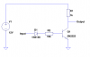
I have read about transistors and pull up resistors. I think I am a little out of my league wiring up this from scratch.

I found several voltage level shifters (40109 is the one I'm looking at) that seems to do the job for me.

Any suggestions???

Thanks in advance.
 
You won't get an accurate reading on a multimeter that is calibrated for a sine-wave at 50Hz to 60Hz.
You need an amplifier to make a low voltage signal into a higher voltage signal.
I would use an opamp.
 
Actually, I'm reading the rpms just fine on the multimeter. Correlates with the stock tach OK. It's an automotive multimeter than has a specific high and low tach setting on it.

The problem is driving the aftermarket 12V tach with the low voltage ecu signal.

Or is this what you mean? I can drive the new tach with an opamp...

(Edit- I looked up this noninverting opamp circuit in wilkepedia. https://en.wikipedia.org/wiki/Image:Opampnoninverting.svg#filelinks)
 
Last edited:
Is the output AC or DC?

Does it just look at the frequency, voltage or both?

Would it matter if the out put from the tach is inverted; i.e. will it still work if the wires are swapped round?

If all you need to do is convert it to a 12V squarewave and you're not bothered about the phase and duty cycle then this circuit will do.
 

Attachments

  • Tach buffer.png
    Tach buffer.png
    12.9 KB · Views: 1,946
Last edited:
Ecu siganl output is DC. (I hope. Does anyone know of a cheap oscillascope I can buy???)

The new tach looks at frequency but also requires 12V (or close to it) to drive it.

The duty cycle (on/off) of the ecu signal decreases with rpms. About 95% on at idle or 1300rpm (only 21Hz). I think inverting this won't be a problem.

Yes, that's one of the circuits that I came across looking up transistors. As well as the one that grounds the load through the transistor. Unfortunately I do not have access to the tach sginal ground. Only the common ground for the new tach.

My concern is the amount of current that the base draws (or leaks, I'm not sure of the terminology). I don't know how much current the ECU signal can source. Is this something I should be worried about?

Am I correct in thinking that transistors are primarily used to "amplify" current? Or can they be used in this manner to amplify voltage as well?
 
Last edited:
If the output from your tach is a sinewave then the output from this circuit will decrease in duty cycle with increasing input frequency.

You can increase R1 to 100k and R2 to 1M but then the load created by the EC might be a problem.

Another option would be to omit D1, reduce R2 to 100R, keep R1 at 1k, and change Q1 to 2N7000 which is a MOSFET and has a very high gate resistance >100M. This will only work if the output from your tach is at least 3V peak, I assumed you're talking about RMS when you said 3V to 5V.
 
I'm sorry. When I said the new tach looks at frequency, does that imply that it is a sine wave?

The new tach looks at voltages. Each time the voltage switches from ground to 12V(or the other way around) it counts as one revolution. I guess I was thinking of frequency that way.

I really need an oscillascope to characterize the ecu signal I am trying to amplify. I am assuming it is a signal that flips between 5V and 0V. Or a low voltage circuit flipping between 3V and 0V.

How about this voltage level shifter? It's so hard for me to decode exactly what these chips are intended to do...

Here's a link to the datasheet 40109...https://pdf1.alldatasheet.com/datasheet-pdf/view/22306/STMICROELECTRONICS/HCF40109BEY.html
 
Last edited:
The 40109 won't work if the signal is less than 3V.
An opamp will work if the signal is just about anything (a few milli-volts) but we need to know how low it goes and how high it goes.

Half of an LM358 dual opamp can be used. Its input and output can go to ground (unlike most opamps). Its output high voltage is 1.2V less than its supply voltage so if the supply is 13.8V then its output high voltage is 12.6V.
 
audioguru said:
The 40109 won't work if the signal is less than 3V.
An opamp will work if the signal is just about anything (a few milli-volts) but we need to know how low it goes and how high it goes.

Half of an LM358 dual opamp can be used. Its input and output can go to ground (unlike most opamps). Its output high voltage is 1.2V less than its supply voltage so if the supply is 13.8V then its output high voltage is 12.6V.

Seems like the opamp would be the easiest way to go.

I'll look up the specifications and how to set the switch point (sorry for the incorrect terminology). Wonder if there will be any issues with current draw from the input? https://en.wikipedia.org/wiki/Image:Opampnoninverting.svg#filelinks

And I'd be willing to bet 10.8V is enough to drive the new tach as well.

Thanks!

Any problems converting the DC digital tach signal from the ecu to an analag device? Sorry for my ignorance.
 
Last edited:
It looks like the LM 358 has a supply minimum of 3V as well. :(

(Edit- Sorry, misunderstood :rolleyes: )
 
Last edited:
It has a minium supply voltage of 3V, not a minium input voltage of 3V - big difference.
 
jcw said:
It looks like the LM 358 has a supply minimum of 3V as well.
It doesn't matter because your supply voltage for it is the 13.8V fully charged battery voltage. Then it amplifies the signal.
The 40109 doesn't amplify so it won't do anything if its input voltage is too low.
 
What about using a comparator with a reference signal at about 2.5V (1/2 5V) and a 12V supply voltage?

This seems to be the most straightforward way of doing this. But I'm sure I'm missing something.

LM211 for a wider operating temp. low 150nA input current.
 
Last edited:
jcw said:
What about using a comparator with a reference signal at about 1.5V and a 12V supply voltage?

This seems to be the most straightforward way of doing this. But I'm sure I'm missing something.

hi,
Thats the way I would do it, if you just want change the signal level from +2V to +12V, use a LM393 comparator, you dont need an amplifier for the input pulse.
Make the Vref adjustable, so that you can change the threshold level.

Do you follow this OK.?

EDIT: something like this.
 
Last edited:
Thanks.:)

Whats the resistor between the comparator an signal for? To limit input current?
 
Last edited:
jcw said:
Thanks.:)

Whats the resistor between the comparator an signal for? To limit input current?

hi,
Do you mean the pullup on the output, if yes, the comp is an O/C output.

If you mean the 470R on the input, from experience, especially in electrically noisy vehicle environments, its wise to have a limiting resistor.
 
Last edited:
So basically the open collector output functions the same as Hero999 transistor solution in post #4.

So in this case, the comparator acts as a "buffer" (again sorry if the terminology is incorrect) that then drives the open collector?

What's the point of all the other stuff (a little tongue in cheek)? Could I just use a buffer and a transistor?

Obviously at this point, I'm realizing there's more than one way to skin a cat. So I'm looking for the most reliable and robust. The environment on a motorcycle means cold and hot and lots of vibration. Fewer components would be beneficial.

Thanks to all that contributed. It has helped a lot.

Can't wait to get into PIC computers and my digital speedometer. ;)
 
A comparator compares two voltages and outputs a high when the non-inverting input is higher than the inverting input. If the inverting input is ted to 0V then it will output a high when the non-inverting input gets above 0V.

A comparator has a very high input resistance so very little current is drawn from the input pins.

A transistor buffer will only turn on when the base voltage exceeds about 0.7V and the input inpedance is not much higher than the base resistor's value.

I've recommend you read up a bit about op-amps, transistors and comparators.
 
Please no laughing...

I went with the voltage comparator (without the capacitor and diode zener? what's that for?) with a pot trimmer.

Here's the circuit on a breadboard...

**broken link removed**

Here's a short video.

https://www.youtube.com/watch?v=viwpftvn2QY

I can gas and mig weld but have never soldered or made a circuit board. The signal cuts out after about 5 minutes so I have some troubleshooting to do yet.

Comments, suggestions?
 
Last edited:
Status
Not open for further replies.

Latest threads

New Articles From Microcontroller Tips

Back
Top