Electro Tech is an online community (with over 170,000 members) who enjoy talking about and building electronic circuits, projects and gadgets. To participate you need to register. Registration is free. Click here to register now.
Welcome to our site! Electro Tech is an online community (with over 170,000 members) who enjoy talking about and building electronic circuits, projects and gadgets. To participate you need to register. Registration is free. Click here to register now.
i'm controlling a 220 V ,50 Hz AC heater using PIC 16F876 (4 MHz clock) by Pulse Width Modulation ... do i need a synchronising circuit ?? if yes, how should i connect it ??
i'm controlling a 220 V ,50 Hz AC heater using PIC 16F876 (4 MHz clock) by Pulse Width Modulation ... do i need a synchronising circuit ?? if yes, how should i connect it ??
There are a number of things here, none of which you really explain?.
Firstly, what type of heater is it?, is it just an element (like a bar fire), or is it one which includes a motor - like a fan heater.
Anyway, aside from that, you don't use PWM to control an AC heater, PWM is a DC technique, not an AC one. For AC it's far easier, and yes you do need to syncronise to zero-crossing. To control an AC heater you use a technique called 'burst fire', which simply means you turn the element ON and OFF over a certain number of cycles, syncronised with zero-crossing to avoid causing inreference.
For an example, with 50Hz mains there will be 500 cycles in a 10 second period, if you turn it ON for 250 cycles, and OFF for 250 cycles, you will get half power - averaged over a 10 second period, which is usually perfect for a heater, with it's large thermal inertia. By using a 10 second period, with 500 cycles, you can adjust the power with 0.2% resolution, which is going to more than enough.
You can either count the incoming cycles, or simply use a delay loop for the timing - but with a delay loop you will have to wait for zero-crossing before turing the heater ON.
i'm controlling a 220 V ,50 Hz AC heater using PIC 16F876 (4 MHz clock) by Pulse Width Modulation ... do i need a synchronising circuit ?? if yes, how should i connect it ??
i'm controlling a 220 V ,50 Hz AC heater using PIC 16F876 (4 MHz clock) by Pulse Width Modulation ... do i need a synchronising circuit ?? if yes, how should i connect it ??
I would suggest an opto-coupler feeding a triac, this will isolate the PIC circuit from the mains.
You can actually buy opto-coupled triacs with in-built zero-crossing circuits, these can simply feed larger triacs. This would reduce your PIC section to just turning a pin ON and OFF at the required ratio.
Have a look at the datasheet here https://www.fairchildsemi.com/ds/MO/MOC3020-M.pdf, which gives examples of how to use an opto-isolated triac - this isn't the version with in-built zero-crossing, and you would need to switch at the correct time. Presumably a datasheet on the zero-crossing version is available from the same site?.
Have a look at the datasheet here https://www.fairchildsemi.com/ds/MO/MOC3020-M.pdf, which gives examples of how to use an opto-isolated triac - this isn't the version with in-built zero-crossing, and you would need to switch at the correct time. Presumably a datasheet on the zero-crossing version is available from the same site?.
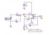
I'm doing a similar project where I use triacs to control the heater.
The zero crossing circuit is connected to secondary of 120:10 transformer (in this schematic I'm using 8V AC source).
The output of zero crossing circuit is fed to the pic (via interrupt) which controls the current amount within the heater (via firing angle). Like Nigel said, it is important to isolate the triac from the pic by using an optocoupler.[/img]
This site uses cookies to help personalise content, tailor your experience and to keep you logged in if you register.
By continuing to use this site, you are consenting to our use of cookies.