Continue to Site

Welcome to our site!

Electro Tech is an online community (with over 170,000 members) who enjoy talking about and building electronic circuits, projects and gadgets. To participate you need to register. Registration is free. Click here to register now.

  • Welcome to our site! Electro Tech is an online community (with over 170,000 members) who enjoy talking about and building electronic circuits, projects and gadgets. To participate you need to register. Registration is free. Click here to register now.

"Contraption" Project: Scratch build motor belt/chain drive w/ variable for/rev speed

Status
Not open for further replies.

adambowersva

New Member
I am working on a project/concept thats been in my head for a long time and need some guidance. I have very little if any electrical engineering know how and am a bit stumped. So any help would be great. Obviously try to keep it as layman as possible as my head is spinning already from some of these threads.

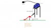
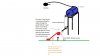
I am trying to design a contraption that has the capability to pull a weight of about 30-50lbs UP a distance of approx 18" and hold for any necessary period of time, then return that weight DOWN to it's original location. It would need to be able to accomplish this task within the time frame of approximately ONE (1) second in either direction. However, I would like to have the acceleration/deceleration in each direction be variable via a throttle mechanism so it could optionally be slowed/sped up a bit as desired.

I was thinking to have this powered by an electric motor so one thing I need to know is what power/size motor would be necessary to carry out this task keeping the weight being pulled, the distance covered, and the time window necessary in mind.

I would think I am going to need a motor, a belt or chain drive, a throttle, and some sort of speed controller. Lately, I have been wondering if stripping an electric scooter would provide many of the necessary parts, but not sure if it will meet the necessary requirements or not.

Some of the other concerns are a motor that can meet the speed needs with the weight requirement, be able to "hold" the weight in place, and reverse it all in a controlled adjustable "on the fly" manner via preferably some sort of thumb/finger operable throttle.

Any guidance any of you can lend in this pursuit of contraption insanity would be greatly appreciated. I also would like ot be able to keep the contraption as small as possible, but low cost, and 12V battery operated.

Thanks so much for the help.
 
Last edited:
The scooter idea sounds good. 18 inches per second is only slightly more than 1 mile per hour. Scooters tend to be able to do 5+ per hour, not sure about acceleration or deceleration, but I'd say it'd be able to do it easily, the power controls and actual controller would be more complicated. 1MPH might not sound like much, but smoothly accelerating and decelerating to it will require moderate controlling sophistication.
 
Is there a way to adjust the "thumb" throttle and speed controller from an electric scooter to say increase sensitivity or broaden the adjustable incremental range within the early band of speed. Say for example, using your mention, that a throttle had the capability at WIDE open throttle to propel the scooter to 5mph and say it had 5 incremental "clicks" so each was worth 1mph. Is there a way to modify the throttle itself, or the speed controller, to virtually disregard "clicks" 2-5 and expand the sensitivity of "click" 1 to the full throttle travel range so in essence if it was still attached to a scooter the throttle would only accelerate the scooter to 1mph even though it was being turned through all 5 "clicks", but at a more detailed rate of accel/decel???

Here are some examples of some of the stuff I was looking at to give you guys an idea...

Say for example the 24V 250W motor here (would be powerful enough to meet parameters of project and furthermore what affect will it have if I run it at 12V on the performance of the motor?)
Electric Scooter and Bicycle Motors - ElectricScooterParts.com

The CT-201C6 24V 250W Electric Scooter Speed Controller
Electric Scooter Speed Controllers from ElectricScooterParts.com

The Hall-Effect Thumb Throttle With 24V LED Meter
Electric Scooter, Pocket Bike, and Bicycle Throttles - ElectricScooterParts.com


The other questions/concerns I guess I also have about motors like this is how they act while under load and you have them stop. Say throttle is applied to raise the 40lb weight and the weight hits a stop point. If you cut throttle will this then cause the motor to drop the weight or would it maintain the weight up? In the event that it would drop it if power was cut, would there be any ill affect on the motor from you maintaining the throttle and power to hold the object up at the stop point? At that point would lowering the weight back down merely be a matter of slowing releasing the throttle to reduce the power of the motor to control the objects descent?
 
Last edited:
The calculations are pretty easy. I'm going to change to SI units first because it makes it even easier (hope I don't screw up). You have about 20kg and you want to move it about 1/2 meter in one second.

With normal gravity, that's about 100 Joules of work, or 100 watt-seconds. You want to do that in 1 second.

Let's see what it takes to accelerate 20kg to a velocity of 1/2 meter per second. That's (MV^2)/2, or 20*(.5^2)/2 = 20/8 = about 2.5 Joules. Doing that in let's say 1/10 second would briefly require 25 Joules/sec. I think we can expect it to stop due to friction when you remove power.

Summary: To lift the load, you need 100W of motor output, plus another 25W briefly to start it. If you assume the motor rating is continuous 250W input with a peak reserve, and the motor/gearbox is near 50% efficient, then it is about right but with very little to spare. It also assumes that all this is designed with a gear ratio that uses the best spot in the motor operating range.

Worm gears are usually good for resisting the tendency to fall when power is released.

Don't forget that you said a 12V system but you showed us 24V motors as examples of what you're looking at.
 
Last edited:
Yeah, the examples used are 24V systems as I had just gotten the idea to use the scooter parts as they seem to fit to my application with the least need for modification or custom fabrication. Finding a 12V motor isn't difficult, but I hadn't yet seen a speed controller or suitable throttle assembly for 12V applications that would work as well as the scooter parts seem likely too...then again I hadn't looked that far into them at and am in process of doing so now. If you had some suggestions that would be great. Thsi contraption is going to need to be able to run mobile which is why I figured on running it via power through a car cigarette lighter plug....herego the need for 12V I guess, but am open to suggestion on that as well.

Or, isn't it possible to modify the 24V equipment to operate at 12V? If so, what affect would this have on the motor performance/reliability?

Further, I like what you mentioned about worm gears. I hadn't thought about that option. The question though is gonna be about how to then get the 40lb weighted load to return to the "lowered" position.

In actuality the majority of the 40lb load will be caused by spring tension in compressing the spring bringing the load up. So I guess if there was a way to have that load held as long as desired then to control the descent and release/relaxing of spring tension back to the lowered position I guess that is what I would be looking into trying to do somehow as well.

The area where I am mostly stumped, aside from getting the appropriate motor/controller/throttle setup, is in the controlling of the descent. The raising of the weight/compression of the spring doesn't have to be as exact as to the variability of the speed so long as it is relatively quick. What I really need the most control over is the descent/decompression of the weighted spring assembly. I need to be able to slow/speed up the descent/decompression variably throughout the 12-18in descent distance.

Thanks for the help and guidance so far. I look forward to more =)
 
Last edited:
Also, another big concern I am having is having the motor application in such a way that the weight can be held up/spring compressed for any period of time without causing damage to the motor as I would think maintaining power to the motor to hold the weight up/spring compressed without any further travel would cause eventual damage to the motor would it not? What would be a good way of maintaining this hold without causing damage? Worm gears were one idea presented, but I don't know about being able to reverse the direction/decompress the spring/lower the weight with worm gear in place as they seem to like going in one direction and not the other.
 
If you use a worm gear, plan on having to reverse polarity to the motor and driving it down. The full load can rest on the drive shaft worm and it won’t move; there is just too much friction and mechanical advantage.
 
No, worm gears work in both directions. Think of a crane or tow truck winch. Short of using some kind of ratchet to lock the cable drum, a worm gear is the best way of holding a load. Plus it will hold at any position, where a ratchet is limited by the notches in it's mechanism.
 
So what you guys are saying is that even with a spring loaded weight lifted of approx. 40-50lbs that was lifted by say a 300W motor (to give the extra necessary "elbow room" in needed power) the worm gear will hold the loaded weight in place indefinitely until power is applied in the opposite direction to draw the weight back down and uncompress the spring, right? If this is the case then the worm gears are sounding more and more like the way to go for gearing =).

Reversing the polarity seems like it should be a fairly easy process right? As the majority of motors I have looked at (mostly being from that scooter realm) can eaily reverse directions by revering polarity. Wouldn't this process be easily controlled by an existing electronic speed controller or no? I'm starting to wonder if some of the speed controllers designed for RC or golf cart applications would work for this process.

Thanks for the continuing help in these recently addressed issues as well as others previously placed that are still under ponderance. =)
 
New question that if works with my thinking may simplify process but need clarification. If you run an electric motor to pull the weight and the weight reached it's stop point where it can go no further, yet power is still applied to the motor to hold the weight for a period of up to say a few seconds will this eventually cause damage to the motor? I understand worm gears will hold the weight once power is removed, but they from what I'm looking at cause a good amount of drivetrain inneffeciency and power loss. Further, finding a controller that will allow reversal of motor polarity to power the motor the other direction is limiting options greatly.

So my thinking is if no damage is caused to the motor by continuing to run for a few seconds even though the shaft won't spin anymore and then backing off on the "throttle" would thereby control the lowering/decompression of the weight back to original start position. Is this feasible or not really a good idea?

Sorry I keep adding stuff to the pot....just thinking out of the box and exploring all the potential options....
 
Stalling a DC motor for a 'few seconds" is not good.

Try to re-word your problem statement to use Mass and Force properly instead of using Pounds for both (damn imperial measurement system) we (and you) might be able to sort it out better. (When a pound is mass, divide it by 2.2 and call it kg, when it's a Pound of force, multiply it by 4.4 and call it Newtons.)

Can you draw a diagram?
 
Where is this spring in the scheme of things? A worm gear is usually pretty powerful, you could break something if it isn't being monitored while in use. It's not a good idea to just let something run while it's at its limit, it will put a strain on the motor/gearbox, the cables or the frame work of your "contraption."

How about a sketch to show what your really after? That will help use better help you. what country are you in?
 
"Contraption" ;) Sketch

Okay gentlemen, I guess you are right a sketch would certainly make things easier to understand so here you go. It's definitely a rough sketch done in Microsoft PAINT, but hopefully you get the idea of what I am imagining.

The lever or "weight" that is being pulled is marked in red and you can now see where the spring comes into the picture. So as you can see it's not the physical weight of the object that is creating the load on the motor. Most of the mass the motor is pulling on is to overcome the spring weight.

Any further guidance you guys can lend would be a great help. Thanks a million to those sticking with me through this puzzle. =).

P.s. to shortbus...I am located just west of Washington DC in the good ol US of A.
 

Attachments

  • Contraption Sketch.jpg
    Contraption Sketch.jpg
    45.9 KB · Views: 280
Last edited:
Reworded to hopefully distinguish between Mass and Force.
The lever ----- that is being pulled is marked in red and you can now see where the spring comes into the picture. So as you can see it's not the mass of the object that is creating the load on the motor. Most of the force the motor is pulling on is to overcome the spring force.
You are still using Mass, Weight, and Force interchangeably. This problem will be unsolvable until you understand the difference.
 
Reworded to hopefully distinguish between Mass and Force.You are still using Mass, Weight, and Force interchangeably. This problem will be unsolvable until you understand the difference.

Sorry about the continued confusion. I was hoping the sketch would take on a "picture worth a thousand words" element for me. Ur rewording seems accurate and appropriate to me.

From my understanding the only real in this project resides in the weight of the lever which is minimal. The majority of the necessary energy definitely comes from the force that is necessary to compress the weight of the spring. The decompression of the spring seems to me to require less force but definitely requires more control due to the necessity to keep the spring decompression and the lifting of the levers mass controlled and variable.
 
Is this some kind of sex toy or what?

Not that there's anything wrong with that...
 
Is this some kind of sex toy or what?

Not that there's anything wrong with that...

Lol, unfortunately (or fortunately depending on who u are) NOT. Thanks for the laugh though. U certainly brought a new dynamic to this technical conversation. ;)
 
Hi

Have you considered a "lead screw" like the ones that drive a lathe feed. You get very fancy ones driven with reciprocating ballbearings or simple square thread screws. For the rate you are talking of a coarse pitch an a fast motor. Leadscrew - Wikipedia, the free encyclopedia

Couple this directly to a d.c. motor through a coupling or gears etc. Consider a linear encoder and or or limit switches and it may turn out to be a simple solution. You could also consider a d.c. drive that allows you to program a ramp up and down in speed at both ends of the scale.

Andrew
 
Okay gentlemen, I guess you are right a sketch would certainly make things easier to understand so here you go. It's definitely a rough sketch done in Microsoft PAINT, but hopefully you get the idea of what I am imagining.

The lever or "weight" that is being pulled is marked in red and you can now see where the spring comes into the picture. So as you can see it's not the physical weight of the object that is creating the load on the motor. Most of the mass the motor is pulling on is to overcome the spring weight.

Any further guidance you guys can lend would be a great help. Thanks a million to those sticking with me through this puzzle. =).

P.s. to shortbus...I am located just west of Washington DC in the good ol US of A.

Your over complicating the "contraption".

If you want to lift the weight the spring is just adding another amount of weight to the job.

If you want to compress the spring the weight is not needed.

The reason I asked where you lived is sometimes people ask for help, and if you source something from the US it's not available where they live.


Maybe if you explain what the final out come of this machine is, I mean what is it going to do, you will get more help. I will help as much as I can with how to do it, but without knowing for sure what your trying to accomplish it's hard to give a real answer.
 
I have added a bit to the sketch to explain a bit better hopefully for clarification. The steel cable through the eyelet is intendeed to pull down on the lever as it wraps around the rod in a similar fashion to how a winch would operate.

As for the spring, unfortunately, it and the lever are an already existing assembly. i am trying to design this contraption to power them instead of manual operation. Therefore, I can't eliminate the spring as it would make the lever impossible to operate manually as it would no longer return to the up position. The spring compresses as the lever is pushed down and decompresses as the lever comes up.

To Andrew: No, actually I never thought about a leadscrew. Thats quite an idea. I'll have to look into that option more. Similar to the operation of a scissor jack and would actually function seems like a big worm gear basically =). Would just have to find some way to make that work like a jack, but without the expansion of pieces around it as it rides the screw, as my surrounding clearance will be pretty tight.
 

Attachments

  • Contraption Sketch.jpg
    Contraption Sketch.jpg
    67.5 KB · Views: 258
Last edited:
Status
Not open for further replies.

Latest threads

New Articles From Microcontroller Tips

Back
Top