Hello Everyone, I need help with this project. The files are attached. I would like someone to tell me in details, how does the main circuit and the control circuit work. e.g: When Sb1 is pressed, then ... energises, etc etc.
1.1 control requirements and technical parameters
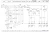
1. The main motion and the feed movement of the lathe are driven by motor M1.
The main function are positive and negative rotation, inching and stop by electric braking.
2. Cooling pump drag by motor M2, direct starting, one-way position.
3. The fast moving of the knife shelf cutter is drag by motor M3. One-way inching.
4. Necessary protection and interlock is required.
5. Local illumination.
6. The power of the motor:
M1 model: Y200L-4, power: 30kw, rated speed: 1470r/mim, rated current: 56.8A,
rated voltage:380V
M2 model: JCB-22, power: 0.15kw, rated speed: 2790r/mim, rated current: 0.43A, rated voltage:380V
M3 model: Y90L-2, power: 2.2kw, rated speed: 2840r/mim, rated current: 4.73A,
rated voltage: 380V
And How to explain(writen) how to:
2. design circuit
2.1 design main circuit
2.2 design control circuit
2.2.1 control M1
1. positive and negative rotation
2. positive inching
3. stop by electric braking
2.2.2 control M2
2.2.2 control M3
2.3 local illumination circuit
Thank you so much for your kind help,
Cheers
1.1 control requirements and technical parameters
1. The main motion and the feed movement of the lathe are driven by motor M1.
The main function are positive and negative rotation, inching and stop by electric braking.
2. Cooling pump drag by motor M2, direct starting, one-way position.
3. The fast moving of the knife shelf cutter is drag by motor M3. One-way inching.
4. Necessary protection and interlock is required.
5. Local illumination.
6. The power of the motor:
M1 model: Y200L-4, power: 30kw, rated speed: 1470r/mim, rated current: 56.8A,
rated voltage:380V
M2 model: JCB-22, power: 0.15kw, rated speed: 2790r/mim, rated current: 0.43A, rated voltage:380V
M3 model: Y90L-2, power: 2.2kw, rated speed: 2840r/mim, rated current: 4.73A,
rated voltage: 380V
And How to explain(writen) how to:
2. design circuit
2.1 design main circuit
2.2 design control circuit
2.2.1 control M1
1. positive and negative rotation
2. positive inching
3. stop by electric braking
2.2.2 control M2
2.2.2 control M3
2.3 local illumination circuit
Thank you so much for your kind help,
Cheers
Attachments
Last edited:

