Continue to Site

Welcome to our site!

Electro Tech is an online community (with over 170,000 members) who enjoy talking about and building electronic circuits, projects and gadgets. To participate you need to register. Registration is free. Click here to register now.

  • Welcome to our site! Electro Tech is an online community (with over 170,000 members) who enjoy talking about and building electronic circuits, projects and gadgets. To participate you need to register. Registration is free. Click here to register now.

CLC filter analysis help

Status
Not open for further replies.

qa9b

New Member
Hello all,

I'm designing an unregulated power supply filter and trying to make sense of my calculations.

Obviously, the goal is to minimize 120Hz ripple after rectification. Some use a single capacitor, some an RC, some a CRC... etc.

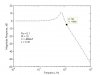
I've put together a 3-pole filter (CLC) and have worked out the transfer function. Source and load resistances are considered. The eqn and a magnitude response graph is attached, but the real takeaway is that I should be seeing about 5dB of attenuation at 120 Hz.

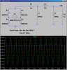
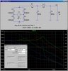
The CLC schematic is attached. This is simulated in SPICE. When the input is a non-rectified 70Vpp sinusoid, I indeed see 5dB of attenuation.

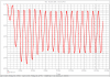
What I'd like help making sense of is the filter output when the input is a rectified sine wave. As would be expected, there is a significant DC component with a ripple riding on top. The peak to peak ripple voltage is almost 4 volts. An image is attached.

I have no way of explaining this mathematically. The ripple seems to have gone from 35Vpp to 4Vpp, which is nearly 19dB of attenuation. Clearly, my 5dB figure no longer applies. I suspect that the disparity has something to do with me ignoring the resulting DC component when the input is rectified.

Is there any shorthand way to calculate the ripple output of this filter like I would with a non-rectified sine wave? The only recourse I can think of would be to find the output in the s-domain and take an inverse laplace transform... this gets disgusting.

Thanks for any help!
 

Attachments

  • CLC schematic.PNG
    CLC schematic.PNG
    21.6 KB · Views: 1,064
  • CLC spice.PNG
    CLC spice.PNG
    146.8 KB · Views: 678
  • CLC_calculated magnitude response.jpg
    CLC_calculated magnitude response.jpg
    19 KB · Views: 742
  • clc_xfr.PNG
    clc_xfr.PNG
    8 KB · Views: 866
You seem to be thinking that the AC component of the output of a full-wave rectifier is a 120hz sine wave.
It is not, there are a lot of higher harmonics as well, consider those and you may get a better answer.

JimB
 
This is a case where using a simulator is more useful than writing equations.

But you have to know what is important: What is the load? Is it purely resistive? Does the load current vary (load regulation)? How much ripple can you tolerate? Do you need to worry about line regulation? Cost? Bulk? Weight? Size?
 
Thanks for the ideas!

I ran some more simulations; attached are the FFTs of a 70Vpp sine wave after rectification as well as that same waveform put through my filter.

Jim, you are certainly correct about the higher frequency harmonics. I realize that after looking at the FFTs. This gives some great information but still, my 5dB figure does not match up.

Mike, I modeled my source and load impedances with resistors, and they are included in my transfer function as R_s and R_l. However, I don't think I've given the equivalent impedance of the diodes a fair characterization. When I stick a source impedance of 2-3 ohms (instead of 0.1) into my transfer function (R_s), the resulting magnitude response matches up a little nicer.

I plan to run some more simulations and hopefully use some sort of buffer to eliminate the diodes from the equation.

My ultimate goal is to arrive at an expression that will estimate output ripple at full power supply load using this CLC topology. The source and load will remain modeled as resistors. From what I've seen so far, you can save some money by using this topology with a rather large inductor. For example, letting C=4800uF and L=4.7mH produces 0.8% ripple under a 3A load. Producing this result with a single capacitor alone would require something on the order of 40,000 uF. Furthermore, it's better than an RC rectification filter because, in that case, there is significant ohmic loss.
 

Attachments

  • CLC - FFT after rectification.pdf
    8.8 KB · Views: 466
  • CLC FFT after filtering.pdf
    8.7 KB · Views: 426
In "brute-force" real-iron power supplies I have seen, the filter inductor is usually in the Henries range; not 4mH. Some use "swinging chokes" that at low DC current levels have inductances of several H.

Here is time-domain sim showing why:

The sims were run with L1 = 4mH (green), 10mH (red), 100mH (lt. blue) and 1H (dk. blue).

I then repeated the sim in the Frequency Domain. To forward bias the rectifiers, V1 is set to 30Vdc, with 1V of AC riding on that to check the response of the CLC filter. Note the peaking that occurs for low values of L1. Also note the magnitude of the attenuation at 120Hz with the four different values of L1.

When you consider the cost and bulk of a proper Filter inductor (Choke), you will find it is cheaper to use bigger capacitor(s) and an electronic regulator...
 

Attachments

  • FWF.jpg
    FWF.jpg
    198 KB · Views: 565
  • FWFac.jpg
    FWFac.jpg
    187.1 KB · Views: 508
Mike,

Thanks for that sim. The smarter option definitely seems to be an electronic regulator. Especially one which switches at very high frequency, where filtering components can be relatively small.

Just for any curious readers... I believe I found the error in my logic when I was trying to explain why I was seeing much more attenuation in full-wave rectified 120Hz ripple than my equation predicted... it's because of the diodes. They only allow current in one direction. Duh. It completely changes the equation. When I removed the diodes and used an ABS function in spice to perfom the rectification, the ripple came out as would be expected (within 1 dB of my equation). Without the diodes, the source can discharge the filtering components.
 
Status
Not open for further replies.

Latest threads

New Articles From Microcontroller Tips

Back
Top