Electro Tech is an online community (with over 170,000 members) who enjoy talking about and building electronic circuits, projects and gadgets. To participate you need to register. Registration is free. Click here to register now.
Welcome to our site! Electro Tech is an online community (with over 170,000 members) who enjoy talking about and building electronic circuits, projects and gadgets. To participate you need to register. Registration is free. Click here to register now.
Hero is correct, charging it through a resistor from 0% to 100% charge will only be 50% efficient.
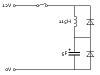
The correct way to charge up a capacitor while maintaining efficiency is to use an inductor and a diode in series with the cap. The only losses will be diode losses. It's in there mainly to prevent backflow of current into the inductor after the cap reaches peak voltage (i.e. it's there to stop the oscillation after 1/2 sine wave).
And yes, the inductor will be large, 18-20 Henries. It will also charge the cap up to TWICE the supply voltage! <- important to remember.
That inductor value is so huge, I would probably go with something else.
I've done this exact thing using a two switch buck/boost type converter. I had to charge it up to 16v from a 12v system, hence the boost part. It worked really well, although I could never get a board made to handle the 30A I was trying for. But that's another issue entirely.
Is this really worth the hassle for a few joules of energy dissipated as heat? 5 Farads is not all that much power, 1 amp for 5 seconds.
Put a 10 ohm 1 - 2 watt wire wound resistor in series with it and accept that it will get slightly warm for a few seconds while it recharges. Unless this is being cycled from full charge and full discharge and back every minute or so I doubt you will ever have enough heat build up in the resistor need to worry about.
Yes and the resistor has to absorb 30 Joules over a period of about 5 seconds while it charges. Thats well within the working capacity of a 1 watt wire wound resistors surge capacity. It will get hot but not to the point of burning out.
If the resistors top end heat limit is and issue use a 3 - 5 watt ceramic resistor or several resistor ganged together.
No, I'm saying a linear constant current source is no more efficient that a resistor because a 1F capacitor charged to 1V will store 0.5J, yet it will take 1J to charge from 1V source powering a linear constant current regulator.
Sorry, I probably didn't explain the formula I previously posted well enough.
Ein = Energy provided by the power supply = 1J
E(c) = Energy stored in the capacitor. = 0.5J
The size of the capacitor or current makes no difference, if you look at the graph of it charging, the area on the top side of the graph is still equal to the area on the bottom.
In practise, a linear regulator will be less efficient than a resistor because it will have a certain drop out voltage.
I also looked at a switcher that can maintain the 'charging' voltage a small
amount above the cap voltage though a small sense resistor and found that
the power lost in the resistor is greatly reduced. Without trying too hard
for example a 0.1v voltage differential and a 0.1 ohm resistor over 1 second
(assuming a quick charge time) uses only 0.1 J. To contrast, the cap stored
0.5 J in that time.
That's basically how i charge my Li-ion batteries too for the last few years
or so. The other nice thing about a switcher is that it can often take a wide
range of input voltages without too much difference in operation. My charger
for example can work with wall warts of 9vdc to about 24vdc, and even will
still charge (slower) with a regular non regulated 6vdc wall wart. Thus, i
can grab any wall wart i have laying around (with same connector) and
use it to charge with. Of course that means it will also accept 12vdc from
the automobile too, which makes it even more versatile.
To get this to happen a regular switcher only needs to be (carefully) modified
to regulate current instead of voltage, and then voltage when the current
drops.
I also looked at a switcher that can maintain the 'charging' voltage a small
amount above the cap voltage though a small sense resistor and found that
the power lost in the resistor is greatly reduced. Without trying too hard
for example a 0.1v voltage differential and a 0.1 ohm resistor over 1 second
(assuming a quick charge time) uses only 0.1 J. To contrast, the cap stored
0.5 J in that time.
Yes, a fixed duty cycle buck would work with a fixed input voltage i guess. There's always going to be at least a little resistance, so i was using 0.1 ohms as an example, even though with an actual power supply we might get much lower than that.
PWM, yes, the idea was to monitor (measure) the cap voltage and make the charge 'voltage' just a little higher knowing some series resistance, but i guess if we monitor the current we would only have to change the duty cycle based on what the current is (you know, a regular analog feedback system).
If i understand you right you may be talking about a forward system with no feedback, where the load dynamics are known ahead of time so you only have to generate the same wave over and over again. Im not sure if that would work unless we always discharge the cap completely before starting to charge it again, or at least to some known state.
I havent been working with super caps so i dont know what the max charge current is for any of them, let alone the particular one being talked about here. I guess i could look up some spec's on the web, but i was hoping the OP would state the spec for his exact cap so we would know for sure.
Yes, I think current regulation is probably the best way to go.
It should be very easy, all that's needed is a comparator and a switching transistor.
You could either use hysteresis: turn switch on, allow the current to reach 2.5A, turn off until current falls to 1A or turn the switch off at 2.5A and have a fixed off period.
I've searched through my posts and it turns out that whilst I was away someone's made one of them into an article. I'm flattered but if I'd known that I would've done a better job.
A similar circuit could be used with a couple of modifications to charge a super capacitor.
That looks like a pretty nice circuit, i'll have to take a closer look.
I do have one question though, about the inductor voltage. Did you check to make sure that
the top terminal of inductor can never reverse bias the LED too much, even during the
turn on phase and the turn off phase of operation? Inductors get uncontrolled sometimes like
that during some operating scenarios so i just thought i would ask.
You mention that your bulky resistors got slightly hot, and this seems to be something you don't like, but just how undesirable is it? You describe a situation where it will only happen initially.
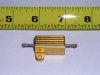
If you can tolerate a slightly but not very bulky resistor, try this.
Get a 5 ohm, 25W resistor of the style shown in the attached photo. When you switch on the power, the capacitor charging current will be 2.5 amps initially. The current will decay exponentially with a time constant of 25 seconds. In 1 minute the capacitor will charge to 91% of final value.
The initial dissipation in the resistor will be 31.25 watts, but it will drop rapidly.
I ran a test, applying a 2.5 amp current continuously (no exponential decay) for 12 seconds. That's a total dissipation of 375 joules. This is more rapid heating than will occur in the capacitor charging scenario. The thermal mass of this style of resistor is such that it takes a while to heat up.
After I disconnected the power, the outside temperature of the resistor continued to increase for a while as the heat generated inside diffused to the surface. The final temperature was what I would call moderately hot. I could easily hold my fingers against it without discomfort. This style of resistor can be bolted to a heat sink or metal panel, but if this only happens once in a while, it's probably not necessary.
This is by far the simplest solution to your problem.
That looks like a pretty nice circuit, i'll have to take a closer look.
I do have one question though, about the inductor voltage. Did you check to make sure that
the top terminal of inductor can never reverse bias the LED too much, even during the
turn on phase and the turn off phase of operation? Inductors get uncontrolled sometimes like
that during some operating scenarios so i just thought i would ask.
The circuit shown in post #25 dissipates just as much power as using a simple resistor to charge the cap. When the switch is closed, the current in the inductor builds up and charges the capacitor. When the capacitor reaches the supply voltage, the current in the inductor reaches a maximum and the energy stored in the inductor is the same as the energy that was delivered to the capacitor.
Next, the top diode becomes forward biased and the current in the inductor slowly decays, losing its stored energy in the diode. When the current in the inductor is low enough that the diode is no longer conducting much, the remaining energy oscillates between the inductor and the capacitor until it, too, is lost.
Only half the energy leaving the power supply is delivered to the capacitor; the rest is lost as heat, as it would be with just a resistor limiting the current.
Some other circuit topology might return the residual energy in the inductor to the power supply with only a parasitic loss.
You're right, I feel kind of silly for missing that.
EDIT:
Adding another diode to stop the inductor short circuiting would solve that but the output voltage will rise uncontrollably unless the circuit is drawing enough current. This could be solved by disconnecting the power to the inductor when the voltage across the capacitor is 8.485V at which point it's storing half the required amount of energy. The capacitor then needs to be directly connected to the power supply to make up for the leakage.
Anyway, it's a silly idea, he should use a buck SMPs.
This site uses cookies to help personalise content, tailor your experience and to keep you logged in if you register.
By continuing to use this site, you are consenting to our use of cookies.