Electro Tech is an online community (with over 170,000 members) who enjoy talking about and building electronic circuits, projects and gadgets. To participate you need to register. Registration is free. Click here to register now.
Welcome to our site! Electro Tech is an online community (with over 170,000 members) who enjoy talking about and building electronic circuits, projects and gadgets. To participate you need to register. Registration is free. Click here to register now.
Let me see if i can get you started and then you can take it from there or come back and ask more questions if you like.
Assumptions:
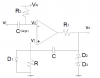
Vs is the source voltage positive, -Vs is the source voltage negative (for the op amp or comparator).
Vd is the clamp voltage of either diode D2 or D3.
CL will be used to indicate C(large) and the other cap will just be called C.
The reference voltage -Vr is greater than -Vd (ie more positive), and +Vd is less than +Vs, and -Vd is greater than -Vs.
Notes:
Note that the output Vo gets clamped to either +Vd or -Vd, except during the recovery period where Vo is changing.
For a very narrow pulse CL looks like a short circuit because it has a large value so the voltage across it changes very little during the pulse period and after the pulse is over.
Quiescent:
V2 is pulled to -Vr, and C is charged so V1=0 (ground), and since V1>V2 then Vo is high which means D3 conducts and clamps Vo to +Vd, and C has a voltage across it equal to Vd with the left side at 0 and the right side at +Vd.
Pulse Applied:
With the narrow positive pulse at Vt, V2 becomes very positive very quickly (t=0+) because CL conducts which causes the output of the op amp to go to -Vs but Vo clamps at -Vd. This puts V1 at negative twice output clamp voltage or -2*Vd because it was charged before this already. That, in combination with V2 being at -Vr, keeps the output of the op amp at -Vs for now. A very short time later after the pulse at Vt goes back low, V2 goes back to -Vr but now V1 is at a very negative level -2*Vd so the output stays negative for now. Next R starts to discharge C back up toward 0v and this takes time T to get to -Vr volts and you can calculate T knowing the voltages and R*C as shown on the question sheet. Just after V1 gets up to -Vr the output goes high again, causing the output Vo to move toward the clamp voltage of Vd. This also causes C to conduct through D1 which means the circuit starts to reset. The time it takes to reset (recover) will be Tr=ln((Vs+Vr)/(Vs-Vd))*R1*C because it takes this time to charge the right side of C back up to +Vd. The circuit is then ready for another input trigger pulse.
The overall effect of the short input pulse is the circuit stretches it out and makes it longer (although of opposite polarity) so it would be considered a one shot circuit.
Let me see if i can get you started and then you can take it from there or come back and ask more questions if you like.
Assumptions:
Vs is the source voltage positive, -Vs is the source voltage negative (for the op amp or comparator).
Vd is the clamp voltage of either diode D2 or D3.
CL will be used to indicate C(large) and the other cap will just be called C.
The reference voltage -Vr is greater than -Vd (ie more positive), and +Vd is less than +Vs, and -Vd is greater than -Vs.
Notes:
Note that the output Vo gets clamped to either +Vd or -Vd, except during the recovery period where Vo is changing.
For a very narrow pulse CL looks like a short circuit because it has a large value so the voltage across it changes very little during the pulse period and after the pulse is over.
Quiescent:
V2 is pulled to -Vr, and C is charged so V1=0 (ground), and since V1>V2 then Vo is high which means D3 conducts and clamps Vo to +Vd, and C has a voltage across it equal to Vd with the left side at 0 and the right side at +Vd.
Pulse Applied:
With the narrow positive pulse at Vt, V2 becomes very positive very quickly (t=0+) because CL conducts which causes the output of the op amp to go to -Vs but Vo clamps at -Vd. This puts V1 at negative twice output clamp voltage or -2*Vd because it was charged before this already. That, in combination with V2 being at -Vr, keeps the output of the op amp at -Vs for now. A very short time later after the pulse at Vt goes back low, V2 goes back to -Vr but now V1 is at a very negative level -2*Vd so the output stays positive for now. Next R starts to discharge C back up toward 0v and this takes time T to get to -Vr volts and you can calculate T knowing the voltages and R*C as shown on the question sheet. Just after V1 gets up to -Vr the output goes high again, causing the output Vo to move toward the clamp voltage of Vd. This also causes C to conduct through D1 which means the circuit starts to reset. The time it takes to reset (recover) will be Tr=ln((Vs+Vr)/(Vs-Vd))*R1*C because it takes this time to charge the right side of C back up to +Vd. The circuit is then ready for another input trigger pulse.
The overall effect of the short input pulse is the circuit stretches it out and makes it longer (although of opposite polarity) so it would be considered a one shot circuit.
"This puts V1 at negative twice output clamp voltage or -2*Vd because it was charged before this already. That, in combination with V2 being at -Vr, keeps the output of the op amp at -Vs for now."
firstly, why V1=-2*Vd ?
secondly, you said " in combination with V2 being at -Vr", why the V2 is at -Vr? V2 becomes very positive very quickly at t=0+, doesn't it?
Lastly, should the output of op amp be clamped at -Vd?
you said "A very short time later after the pulse at Vt goes back low, V2 goes back to -Vr but now V1 is at a very negative level -2*Vd so the output stays positive for now."
If V2= -Vr and V1= -2*Vd
since V2>V1,
shouldn't the output become negative?
"This puts V1 at negative twice output clamp voltage or -2*Vd because it was charged before this already. That, in combination with V2 being at -Vr, keeps the output of the op amp at -Vs for now."
firstly, why V1=-2*Vd ?
secondly, you said " in combination with V2 being at -Vr", why the V2 is at -Vr? V2 becomes very positive very quickly at t=0+, doesn't it?
Lastly, should the output of op amp be clamped at -Vd?
For the quiescent state t=0-, the cap C is charged. The left side is at 0v and the right side is at +Vd. After the pulse, the output goes to -Vd which puts the right side of C at -Vd. With C having it's charge of Vd already and now the output at -Vd, the left side of the cap goes down to -2*Vd because the cap voltage adds to the output voltage: (-Vd)+(-Vd)=-2*Vd.
V2 starts out at -Vr, goes positive, then a very short time later goes back to -Vr (when the pulse which is narrow ends). If you want to consider when the pulse is still positive that's ok, but the positive pulse then holds the output negative and it stays that way until the pulse goes away. So at first the positive pulse holds the output negative, then after the pulse goes away the V2 very negative voltage holds the output negative.
you said "A very short time later after the pulse at Vt goes back low, V2 goes back to -Vr but now V1 is at a very negative level -2*Vd so the output stays positive for now."
If V2= -Vr and V1= -2*Vd
since V2>V1,
shouldn't the output become negative?
"A very short time later after the pulse at Vt goes back low, V2 goes back to -Vr but now V1 is at a very negative level -2*Vd so the output stays negative for now."
The output stays negative because -Vr is greater than -2*Vd. That's the mechanism that holds the output low for a time even after the pulse goes away. The cap C originally has a voltage across it and that adds to the output which makes V1 even lower which means now V1 is down lower than -Vr and so of course the output stays negative.
Note however that the output did not 'become' negative because of this, the output originally becomes negative because of the positive pulse. The response of the output added to the cap voltage is what HOLDS the output low for a time. That's how we get the one shot action.
Let me see if i can get you started and then you can take it from there or come back and ask more questions if you like.
Assumptions:
Vs is the source voltage positive, -Vs is the source voltage negative (for the op amp or comparator).
Vd is the clamp voltage of either diode D2 or D3.
CL will be used to indicate C(large) and the other cap will just be called C.
The reference voltage -Vr is greater than -Vd (ie more positive), and +Vd is less than +Vs, and -Vd is greater than -Vs.
Notes:
Note that the output Vo gets clamped to either +Vd or -Vd, except during the recovery period where Vo is changing.
For a very narrow pulse CL looks like a short circuit because it has a large value so the voltage across it changes very little during the pulse period and after the pulse is over.
Quiescent:
V2 is pulled to -Vr, and C is charged so V1=0 (ground), and since V1>V2 then Vo is high which means D3 conducts and clamps Vo to +Vd, and C has a voltage across it equal to Vd with the left side at 0 and the right side at +Vd.
Pulse Applied:
With the narrow positive pulse at Vt, V2 becomes very positive very quickly (t=0+) because CL conducts which causes the output of the op amp to go to -Vs but Vo clamps at -Vd. This puts V1 at negative twice output clamp voltage or -2*Vd because it was charged before this already. That, in combination with V2 being at -Vr, keeps the output of the op amp at -Vs for now. A very short time later after the pulse at Vt goes back low, V2 goes back to -Vr but now V1 is at a very negative level -2*Vd so the output stays negative for now. Next R starts to discharge C back up toward 0v and this takes time T to get to -Vr volts and you can calculate T knowing the voltages and R*C as shown on the question sheet. Just after V1 gets up to -Vr the output goes high again, causing the output Vo to move toward the clamp voltage of Vd. This also causes C to conduct through D1 which means the circuit starts to reset. The time it takes to reset (recover) will be Tr=ln((Vs+Vr)/(Vs-Vd))*R1*C because it takes this time to charge the right side of C back up to +Vd. The circuit is then ready for another input trigger pulse.
The overall effect of the short input pulse is the circuit stretches it out and makes it longer (although of opposite polarity) so it would be considered a one shot circuit.
1. The other end of R is connected to ground, so if the left side of C is negative R will tend to charge the left side up toward 0v. Perhaps i should have specified the left side of C.
2. The time is calculated by knowing the voltage across C just before this time period starts and the R1*C time constant and that the output of the op amp went to +Vs. I am assuming you've done a little circuit analysis with resistors and capacitors before this but if not we can look at a few R and C circuits so you can get the hang of it. The voltage across C is the result of the left side charging back toward 0v but the output changes state again before that, when the left side reaches -Vr. That means we know the left side of C is at -Vr and the right side is charging through R1 (because of +Vs) toward +Vd. Knowing these two voltages and R1 and C allows us to calculate the time period. The diode D1 conducts and it is considered perfect so it has zero resistance so the resistance and capacitance responsible for this time period is R1 and C (note R would be considered shorted out at this point). The output of the op amp BTW went to +Vs, so we have a voltage source Vs charging a capacitor C through R1 where the cap had a voltage of Vr across it just before the time period started but the time period ends when the right side finally reaches +Vd. And yes, this would be considered the recovery time i believe because if another pulse occurred before this 'recovery' time period was completed the circuit would not function as designed because it would put out a shorter pulse then desired. This of course means that for an input train of pulses they would have to be separated by some minimum time period or else some of the one shot output pulse widths would be shorter than others and this is usually not desired.
Note the recovery time is over when the right side of C charges back up to +Vd, and that takes us back to the original quiescent state of the circuit.
Note also we assume that R>>R1 and this is most reasonable for this kind of circuit.
There is one caution when calculating the recovery time, and that is that we have to carefully check the polarity of the voltage across the cap or we wont get the time period right. Funny thought, they seem to be asking for the "recovery time constant" which would be simply R1*C. The recovery time period itself however is as given in my previous post as you noted but they may not actually require that calculation except maybe to plot the entire output wave.
The best thing for you to do (since they ask that anyway) is to map out the complete wave for each node starting from the original quiescent state. That will help you understand the complete operation of this circuit and make it clearer what the time periods should be (there are of course two important time periods for this circuit).
how do you calculate the recovery time constant again?
And how about the pulse width T?
should I use the equation Vc(t)=V(final) - [V(initial) - V(final)]*exp[-t/(R*C)] ???
find the time when Vc= -Vr ??
what should be V(final) and V(initial) ??
The time constant is simply R1 *C, because C is charging through R1 from the output of the op amp.
Here is the equation for a cap charging through a resistor where the cap has some initial voltage V2 and V1 is the source voltage:
V3=(V1-V2)*(1-e^(-t/RC))+V2
and the solution for t is:
t=RC*ln((V2-V1)/(V3-V1))
Below we'll call R1 just R because it makes the text easier to read...
Ok, we start with:
V3=(1-e^(-t/RC))*(V1-V2)+V2
solve for t:
t=RC*ln((V2-V1)/(V3-V1))
replace V2 with -Vr:
t=RC*ln((-V1-Vr)/(V3-V1))
inside the ln() multiply top and bottom by -1:
t=RC*ln((V1+Vr)/(V1-V3))
replace V1 with Vs:
t=RC*ln((Vs+Vr)/(Vs-V3))
replace V3 with Vd:
t=RC*ln((Vs+Vr)/(Vs-Vd))
replace R with R1:
t=R1*C*ln((Vs+Vr)/(Vs-Vd))
and we have the required equation.
There's a problem however. The initial cap voltage here is not -Vr it is actually Vd-Vr because just before this period starts the right side is at -Vd and the left side is at -Vr, which means the total voltage across the cap is Vd-Vr. Thus if Vr=3v and Vd=8v, the initial cap voltage is -5v not -3v. Sorry about that.
This means you will have to rework the equations above using this new information.
We will ultimately test all the equations in a circuit simulator in the end too.
The cap C is originally charged with 0v on the left and +Vd on the right. That means it has Vd volts across it, with the left side negative and the right side positive. Now when the output of the op amp goes to -Vs, the right side of C gets clamped to -Vd and that means the left side jumps to -2*Vd (which they show as 2*Vo). This means we now have a cap with the right side -Vd and the left side -2*Vd, so we are now discharging the left side of the cap back up toward 0v, so we can use the equation:
Vr=2*Vd*e^(-t/RC)
and solving that for t we get:
t=R*C*ln(2*Vd/Vr)
and since R is really R1 here we end up with:
t=R1*C*ln(2*Vd/Vr)
Let me double check this first though.
Yes ok this looks correct, although the left side of the cap would look like it was charging from -2*Vd to -Vr.
BTW i made a small error when typing the last post.
In the circuit, the last equation would be:
t=R*C*ln(2*Vd/Vr)
and not
t=R1*C*ln(2*Vd/Vr)
as posted before, as R is discharging the cap not R1. I made the mistake of thinking we were still working on the 'recovery' time period. The recovery time period Tr depends on R1 but he normal time T period depends on R instead. So sorry
One interesting side note with this circuit is that the rise time of the output could be rather slow if R1 is too large.
This site uses cookies to help personalise content, tailor your experience and to keep you logged in if you register.
By continuing to use this site, you are consenting to our use of cookies.

")