Pravin Gosavi
Member
Hello everyone. I am doing a project in which I use a buck converter to convert high vtg to low vtg.
Actually the input to the buck converter is from a solar panel which puts out 560 mA constant current and 34 V.
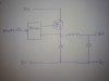
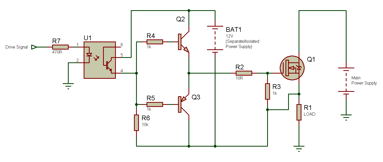
And output is a 12V lead acid battery. The N- Channel mosfet is used at high side and is driven by an isolated driver (I used separate 12V battery to drive the MOSFET). I used PIC controller to give pulses at 20 KHz. I also used pot to vary duty cycle. I calculated inductor value from some website (there was an onlime calculator) By calculations it was 40 mH. I my have made inductor using a ferrite core transformer (taken out from 24 W old power supply ) Diode used is a fast recovery diode.
So my problem is when everything is connected properly the output of buck doesn't give out enough power. The output is pulled down to battery vtg (as expected) And current going into the battery approx. 400-500 mA. And inspite of changing duty cycle power stays (say 500mA × 12 V) 6 W.
And at input side current from panel is 500-600 mA and panel vtg varies with varying PWM ( with pot ) from 12 V ( exceptionally battery vtg) to 34 V. Now power at input as observed is (34 V × 500 mA) 17 W and ouput still remains 6 W ( at battery side).
Plz help. I have read most of the designs available online. Also increased the inductor value to about 90 mH. But nothing worked.
Actually the input to the buck converter is from a solar panel which puts out 560 mA constant current and 34 V.
And output is a 12V lead acid battery. The N- Channel mosfet is used at high side and is driven by an isolated driver (I used separate 12V battery to drive the MOSFET). I used PIC controller to give pulses at 20 KHz. I also used pot to vary duty cycle. I calculated inductor value from some website (there was an onlime calculator) By calculations it was 40 mH. I my have made inductor using a ferrite core transformer (taken out from 24 W old power supply ) Diode used is a fast recovery diode.
So my problem is when everything is connected properly the output of buck doesn't give out enough power. The output is pulled down to battery vtg (as expected) And current going into the battery approx. 400-500 mA. And inspite of changing duty cycle power stays (say 500mA × 12 V) 6 W.
And at input side current from panel is 500-600 mA and panel vtg varies with varying PWM ( with pot ) from 12 V ( exceptionally battery vtg) to 34 V. Now power at input as observed is (34 V × 500 mA) 17 W and ouput still remains 6 W ( at battery side).
Plz help. I have read most of the designs available online. Also increased the inductor value to about 90 mH. But nothing worked.