Continue to Site

Welcome to our site!

Electro Tech is an online community (with over 170,000 members) who enjoy talking about and building electronic circuits, projects and gadgets. To participate you need to register. Registration is free. Click here to register now.

  • Welcome to our site! Electro Tech is an online community (with over 170,000 members) who enjoy talking about and building electronic circuits, projects and gadgets. To participate you need to register. Registration is free. Click here to register now.

Brasilia Espresso Machine Repair - Basic Electronic Help

Wolfcougar

New Member
Hi, I'm new to the forum and I could use some help figuring out what might be wrong with my Italian espresso machine. I have an old Brasilia commercial espresso machine, but I only use it at home. I'm not sure what model it is, but I'm thinking it's a Brasilia Portofino or a Brasilia Lady (the older machines weren't marked). I'm guessing it was made in the 80s or 90s, so it's pretty low-tech. Not a lot of electronic components. I've talked to a few espresso repair shops and old stereo repair shops about fixing the electronics, but the espresso shop is more of a part replacement shop (no electrical techs in-house), and the stereo shops are seemingly uninterested in looking at an espresso machine.

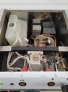
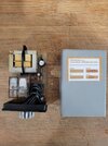
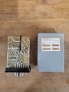
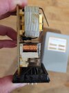
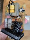
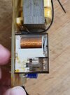
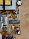
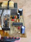
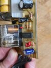
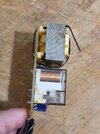
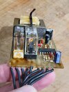
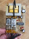
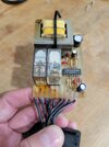
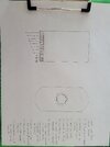
My current issue is that the machine powers on, but the low water level light stays on (regardless of water level in the tank) and that overrides all other functions of the machine. Thus, nothing else is working. No pump, no heat, etc. There is a water level control box (see photo) that has a transformer and a couple of relays in it.

I'm curious if there is an easy way to 1) test the components in the control box and 2) replace them if something is bad? I can solder/replace components, but I need help determining what to replace.

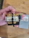
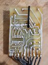
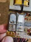
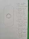
It's pretty basic old school electronics, and I've tried to test some of the components with my multimeter, but I'm no expert and I don't entirely trust my results. The box appears to have been repaired in the past, but the capacitors look good and I don't see any signs of burnt components. My guess is that the transformer has been replaced in the past (see black zip tie and aftermarket manufacturer's sticker), and it needs to be replaced again. If my thinking is correct, the transformer isn't producing enough power to run the board and kick the relays for the various components. It's a 110v AC machine, but the transformer steps down to 12v DC for the relays. Maybe I'm wrong. I tested the transformer with my multimeter and I have 110v service in and about 10.4 volts out. Does that sound right?

I really feel like this is a simple fix, but I'm just not that experienced. I've found fairly inexpensive "water level controls" online that look like they could be a suitable replacement, but again I'm just not certain how this box works.

Appreciate any help or guidance? I really need some espresso! Thanks for your time,
Jeremy
 

Attachments

  • 20230731_105827.jpg
    20230731_105827.jpg
    1.2 MB · Views: 128
  • 20230731_120202.jpg
    20230731_120202.jpg
    1.9 MB · Views: 113
  • 20230731_120155.jpg
    20230731_120155.jpg
    1.8 MB · Views: 118
  • 20230731_120215.jpg
    20230731_120215.jpg
    1.3 MB · Views: 123
  • 20230731_120221.jpg
    20230731_120221.jpg
    1.5 MB · Views: 133
  • 20230731_120226.jpg
    20230731_120226.jpg
    1.3 MB · Views: 125
  • 20230731_105914.jpg
    20230731_105914.jpg
    1.3 MB · Views: 116
There are two electrodes with terminals sticking out the top of the tank, one with an earth wire and the other with a white and brown? wire.

Those appear to be the water level sensing electrodes.
Are they clean, bright metal if you look in the tank? Scale or corrosion could be interfering with the sensing system - or the corrosion in the connections on top?

Other than that, can you trace the white wire?
 
That is correct, rjenkinsgb. Both electrodes are clean and bright. One is ground and the other goes to the electrical control box I mentioned. Wires are also in good shape. I even jumped those wires to eliminate that issue, but there was no change.

I can provide a bit more detail. The machine has two water level indicators: one in the water tank, which you noticed, and one in the boiler. The boiler is a single probe with a single wire going back to the control box, and the boiler serves as earth. Essentially, the control box detects water in the tank and disables the system if it's low in order to prevent burning up the pump. The box also does the same for low water in the boiler in order to prevent burning up the heating element.

I think the water level indicators lead to the separation relays in the box (I think), so low water in the tank would prevent the pump from working and low water in the boiler would prevent the boiler from working. Again. I could be wrong.

I hope this helps.

Thanks
 
OK, can you pull the PCB from the "plug" base and take some more close-up photos, without the link wires covering part of the PCB?

It should come out the locating slot with the wires still connected.

And, can you trace which pins on the 11 pin plug the two active probe wires go to?

There is what I believe is a 4000 series CMOS IC hidden under the bundle of wires & that (or parts of it) will be used to make the level sensors, so most likely one of the components around that has failed, if not the IC itself.

The blue electrolytic cap may have some discolouration near it? Any of the electrolytics could be the culprit as they tend to age and degrade more so that other types of component, in normal operation.
 
Certainly. See attached photos. Let me know if these are sufficient. You are correct, there is an IC under the bundle of wires. There is some discoloration around the blue cap, and near the two relays. I wasn't sure if that was heat damage or just old solder flux. Again, I'm really at the limits of my technical knowledge here.

I'm currently mapping out the wires/pins on the plug base. Apologies, but I'm not sure I understand your question about the "two active probe wires" on the plug? Can you clarify what you mean by that? Would those be the positive/neutral power supply?
 

Attachments

  • 20230805_112047.jpg
    20230805_112047.jpg
    1.1 MB · Views: 103
  • 20230805_112148.jpg
    20230805_112148.jpg
    1.3 MB · Views: 117
  • 20230805_112143.jpg
    20230805_112143.jpg
    1.1 MB · Views: 119
  • 20230805_112117.jpg
    20230805_112117.jpg
    1.3 MB · Views: 115
  • 20230805_112107.jpg
    20230805_112107.jpg
    1.2 MB · Views: 116
  • 20230805_112054.jpg
    20230805_112054.jpg
    1.3 MB · Views: 112
  • 20230805_112039.jpg
    20230805_112039.jpg
    1.1 MB · Views: 116
  • 20230805_112034.jpg
    20230805_112034.jpg
    1.2 MB · Views: 108
  • 20230805_112028.jpg
    20230805_112028.jpg
    1.3 MB · Views: 116
  • 20230805_112010.jpg
    20230805_112010.jpg
    1 MB · Views: 116
OK, I've worked out the sense circuit as best I can, by superimposing the PCB tracks over the component view.

The first three wires from the right are the ones to do with water sensing - can you tell which pins of the module plug each goes to?

Coffee_pcb.png


I've also found what appears to be a schematic of the machine, or at least a similar one using an 11 pin plug-in module?? Can you tell if it is the same one, with the same connections to the module socket?

Coff_Schematic.jpg
 
Fantastic. This is really interesting. I've traced my wires and sketched the following wire/pin locations, as they relate to the plug base and the PCB. After comparing, I do think the schematic you found is correct for my machine. Everything appears to line up. I've also attached a very rough hand drawn schematic of my machine. Please forgive the crude illustration. I was never the artist of the family.

I hope this helps.
Thanks.
 

Attachments

  • 20230805_163349.jpg
    20230805_163349.jpg
    731.1 KB · Views: 104
  • 20230805_163356.jpg
    20230805_163356.jpg
    802.6 KB · Views: 106
  • 20230805_163400.jpg
    20230805_163400.jpg
    602.6 KB · Views: 108
  • 20230805_163413.jpg
    20230805_163413.jpg
    930.5 KB · Views: 102
Are you sure about the wires from 8 & 9 within the module?? Where you have 9 is one of the water sensor pins on the PCB, from what I'd worked out, so more likely wire 8?

It looks like the whole electronic sense circuit is "floating"; it puts out a low voltage AC signal to the ground wire, and senses that AC signal coming back though the electrodes when water is present to give a conductive path.

I'd try changing the three electrolytic capacitors, just on principle that they can degrade.
 
You are correct! I mistakenly switched wires 8 and 9.

Sounds good. I just ordered some new caps and they should be here in two days. I'll swap those out and report back.

Thanks again.
 
Success!! rjenkinsgb, I replaced the three capacitors last night and the machine fired right up! All relays and solenoids seem to be working fine. It's great to have this old machine running again. Thanks again for all of your help. I wasn't getting any help from the local espresso and/or electrical repair shops, so you've also restored a bit of my faith in humanity. Many thanks!
 

Latest threads

New Articles From Microcontroller Tips

Back
Top