Continue to Site

Welcome to our site!

Electro Tech is an online community (with over 170,000 members) who enjoy talking about and building electronic circuits, projects and gadgets. To participate you need to register. Registration is free. Click here to register now.

  • Welcome to our site! Electro Tech is an online community (with over 170,000 members) who enjoy talking about and building electronic circuits, projects and gadgets. To participate you need to register. Registration is free. Click here to register now.

ACremote repair atempt

dejco86

New Member
Hello
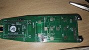
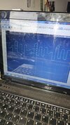
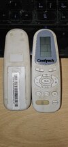
I have a problem. I have an air conditioner that hasn't been used for a while, so the batteries in the remote are also dead. when I put new ones in the remote, the screen on the remote came on for less than a second and then went off. This happens every time I take the batteries out of the remote and put them back in. The contacts are clean. when I connected the oscilloscope next to it, the crystal read 32.700 kHz. I measured with a voltmeter. I also measured the resistors with the numbers on them, they are not bad. I don't know what value resistors have that don't have anything written on them. there are four of them. I don't know about transistors either, one says "J3" and the other two say "L6". On one blue transistor it says 2.50, then there is some funny M mark in a circle and finally the letter S. Does anyone know these values? Or what can i check to identify the problem?
Thank you
1000003816.jpg
 
As always, you don't repair things by randomly trying to test components - you need to fault find. As far as remote controls go common failures would be the ceramic resonator (often with a broken leg due to being dropped), the electrolytic capacitor (either O/C or broken leg again), or the IR LED (again drop damage, may be broken, may just be O/C).

The blue device is the ceramic resonator, and presumably 2.5MHz - make sure it's not broken, and check it with the scope, using a x10 probe (a x1 may well stop it anyway).

There's pretty well nothing else on there to test, nothing else ever really fails - but seriously check the pins on the blue ceramic resonator, that's a prime suspect for drop damage.
 
Another possibility - it looks like it may be a complex, programmable remote with a real-time clock, as it has a 32KHz xtal as well as the main CPU clock resonator?

Some devices like that need a specific reset sequence (eg. two or more specific keys pressed) while you fit new batteries, to clear the RAM of the random values that are left from a cold start. Do you have the owners manual for it?
 
You are absolutely sure you are putting in the new batteries correctly and the new batteries are fresh 1.5 volt batteries? Normally the batteries go in opposing each other. This is how we get 3 volts. The batteries do not go in facing the same direction.

Ron
 
First of all thanks for your response.
As always, you don't repair things by randomly trying to test components - you need to fault find. As far as remote controls go common failures would be the ceramic resonator (often with a broken leg due to being dropped), the electrolytic capacitor (either O/C or broken leg again), or the IR LED (again drop damage, may be broken, may just be O/C).

The blue device is the ceramic resonator, and presumably 2.5MHz - make sure it's not broken, and check it with the scope, using a x10 probe (a x1 may well stop it anyway).

There's pretty well nothing else on there to test, nothing else ever really fails - but seriously check the pins on the blue ceramic resonator, that's a prime suspect for drop damage.
I resoldered the whole board, measured the electrolytic capacitor and it is within normal limits. I measured the blue ceramic resonator on the outer legs, which show 2.5Mhz analog waveform and are offset by half. The central leg is the ground. As for the IR LED, how can I test it?

Another possibility - it looks like it may be a complex, programmable remote with a real-time clock, as it has a 32KHz xtal as well as the main CPU clock resonator?

Some devices like that need a specific reset sequence (eg. two or more specific keys pressed) while you fit new batteries, to clear the RAM of the random values that are left from a cold start. Do you have the owners manual for it?
On the other side of the board is a tile next to which says RESET. Can you delete the entire program for the air conditioner with this?
This device is at least 10 years old, unfortunately I don't have the user manual. I tried to find it on the internet but no luck.

You are absolutely sure you are putting in the new batteries correctly and the new batteries are fresh 1.5 volt batteries? Normally the batteries go in opposing each other. This is how we get 3 volts. The batteries do not go in facing the same direction.

Ron
The batteries have been inserted correctly.
When testing, I use an external power supply.


The image with the display signal is the same on each contact pad. That's all I've been able to figure out so far with your help. If anyone has any ideas, please write them to me. I would not like to buy universal remotes because all the remotes I looked at for purchase do not support the CoolTech company.
Thank you
 

Attachments

  • 414477834_1389069252031207_1273526498105035020_n.jpg
    414477834_1389069252031207_1273526498105035020_n.jpg
    296.4 KB · Views: 79
  • 414571555_7324776484303363_3012644862479818156_n.jpg
    414571555_7324776484303363_3012644862479818156_n.jpg
    264.4 KB · Views: 76
You can check the IR LED by sticking the scope on it, you should see the 38KHz or so pulses on one side of it. If there's no pluses on the LED (with a button pressed) then follow it back to the transistor that drives it, and see if there's any drive to the transistor.

As you've got multiplexing signals in the scope picture, it looks like the chip is running - there will be no danger of wiping the chip by applying a reset, but also there's likely to be no advantage doing so (it resets anyway every time you apply power).
 
Try linking the reset pins, it won't do any harm..

The waveform looks like an LCD drive signal.

From the PCB photo, it appears to use a glass LCD module with "zebra rubber" strips for the connections?
If those or the contact surfaces have the slightest trace of contaminants on them, or the alignment / fixing force is not just right, you will get a corrupted or blank display even if the electronics are fine.


ps. It's a rebranded Vestel aircon from the name on the PCB - there are a vast number of Vestel remote controls around, but I have no idea which model it is.
 
You can check the IR LED by sticking the scope on it, you should see the 38KHz or so pulses on one side of it. If there's no pluses on the LED (with a button pressed) then follow it back to the transistor that drives it, and see if there's any drive to the transistor.

As you've got multiplexing signals in the scope picture, it looks like the chip is running - there will be no danger of wiping the chip by applying a reset, but also there's likely to be no advantage doing so (it resets anyway every time you apply power).
I measured, and there is no signal anywhere. I followed the path to the transistor, where there was also no signal. Then I followed the path leading to the chip, there was no signal there either. I also tried to measure the input signal from the buttons, which was fine when the button was pressed. I assume there is something wrong with the chip. I also tried applying isopropanol to the chip, but it quickly evaporated in one specific place when I added current.

Try linking the reset pins, it won't do any harm..

The waveform looks like an LCD drive signal.

From the PCB photo, it appears to use a glass LCD module with "zebra rubber" strips for the connections?
If those or the contact surfaces have the slightest trace of contaminants on them, or the alignment / fixing force is not just right, you will get a corrupted or blank display even if the electronics are fine.


ps. It's a rebranded Vestel aircon from the name on the PCB - there are a vast number of Vestel remote controls around, but I have no idea which model it is.
I also thought at first that it was just corrosion, that the screen didn't work because of it.
But if the screen doesn't work, you could still turn the air conditioner on or off, I guess.

The brand of this air conditioner is CoolTech, but the model is supposed to be D-9, at least that's what it says on the air conditioner. As i said, I searched the Internet, but no trace of such a climate. It's like it doesn't exist.


I'll try to buy a regular universal remote, but if it doesn't work I'll try to sell it.
Unless there are other options.? What are you suggesting? Do you agree with me about the broken chip?

Tnx
 
OK, I believe the current version of that could be a "YK(R)-C/01E" - about £6 on ebay or less on aliexpress etc.
The are sold under numerous brand names, and include the "YK" in the part number as on your remote circuit board.

eg.
Okay. I bought this remote. I'll report back when I get it and try it.
tnx for now :)
 

Latest threads

New Articles From Microcontroller Tips

Back
Top