Continue to Site

Welcome to our site!

Electro Tech is an online community (with over 170,000 members) who enjoy talking about and building electronic circuits, projects and gadgets. To participate you need to register. Registration is free. Click here to register now.

  • Welcome to our site! Electro Tech is an online community (with over 170,000 members) who enjoy talking about and building electronic circuits, projects and gadgets. To participate you need to register. Registration is free. Click here to register now.

Boosting current without boosting voltage

Status
Not open for further replies.
I was gutting an old PC power supply and I stumbled across a curious little part, a UC3843. I thought it was odd that it was connected to 120V DC (since the input voltage was rectified immediately). It's a High performance current mode controller, and it turns out that they're in a lot of things that need a lot of power. I thought it would be perfect for my radio's power supply since I've already maxed the 12.6-0-12.6V 2A transformer for power. I was wondering if I could connect the UC3843 to boost the current that the transformer can supply without increasing the voltage. It's really important because I have 3 parts that get their power from the unregulated input voltage, the 4700uF filter capacitor (max voltage of 35V DC), the 3 12V regulators (7812), and most importantly an LM339 comparator (max voltage of 36V DC). All 3 are supplied a voltage of 34.2V.

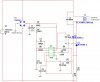
So, if I connect the UC3843 to a circuit similar to the one shown in figure 33 in the data sheet, can I boost the output current of the transformer, without boosting the voltage? I will attach a schematic once I finish it.

http://www.datasheetcatalog.org/datasheet/motorola/UC2843BD.pdf
 
No I don't see it happening. Your current transformer converts mains power to 12 - 0 - 12 Volt @ 2 Amps maximum. First the transformer is rated for 2 amps max. Next at what frequency does your current transformer run at? What would the chip and a mosfet drive it at? Think frequency. Think the frequency a small computer PSU runs at, now thing about your transformer.

Ron
 
Last edited:
I was thinking on the principal of if I increase the frequency, the current output would increase because the transformer would spend more time powering the load than the filter capacitor. Also on the idea that when power is applied to a coil the current spikes, I was hoping that the current spike would transfer to the secondary coil.

And if it's not too much trouble, I found a capacitor in the same power supply, I don't know what it's capacitance is, or it's voltage rating. It reads 400WV (how many volts is that?)
330MF (is that mega-farads? or milli-farads?)

Here is the schematic that I came up with.
 

Attachments

  • Power supply1.JPG
    Power supply1.JPG
    48.6 KB · Views: 650
Last edited:
If I understand, the power supply unit is for a radio. It is better Not to use Switch mode controllers, either current mode or Voltage Mode as you are likely to suffer the QRN created by the supply itself.

How did you get 34V or so Unless you would have used end terminals in a bridge formation?

when you say the current demand, what are the voltages derived, I understand that you have used three LM7812 regulators.
Generally you know, a full wave rectifier is preferable for higher load demands instead of bridge. As such, I would suggest that you may use full wave rectifier using 3 amp schotkey diodes for reducing forward drop and thus the output DC would be higher. After filtering you are expected to get around 17.8 on no load, and while on load, even if you consider 0.4V Drop for the schottkey diodes (each half cycle, only one diode need be considered) you are safely getting at least 13.5V leaving the balance for the copper loss.

Now you might use LDO regulators instead of normal ones to give you 12V and under load distribution method, three such can safely serve your needs.
 
It looks to be a pretty standard SMPSU IC, and I've no idea what the two SCR's in your circuit are doing?.

You should be using an FET as shown in the datasheet, and of course a custom made SMPSU transformer - this would be in addition to (or entirely replace) the existing PSU - you can't 'boost' it.

However, you would be FAR better off redesigning the original circuit correctly.
 
Doesn't the VA rating of the transformer limit the output? You can't get more amps from thin air, only what the transformer is capable of.
 
Under optimization and use of modern components, the losses could be minimized.Thus we can get full efficiency and as transformers are 10% over equipped as safety margin compared to design spec, i feel this could be possible.
If a 120V to 12.6-0-12.6V transformer has to be used, one can always wire the output windings in parallel and use a bridge, so that more current can be expected of it. this is limited by the core dimensions, though. as I have already suggested , it would be better if we can use schottkey diodes and LDO regulators, for a radio power supply.
I hope we can still manage to get a load of at least 40% in excess of the designed capacity.
 
Last edited:
OK, first let's look at your questions here:

And if it's not too much trouble, I found a capacitor in the same power supply, I don't know what it's capacitance is, or it's voltage rating. It reads 400WV (how many volts is that?)
330MF (is that mega-farads? or milli-farads?)

The 400 WV means the capacitor is rated at 400 WV (Working Volts) on some caps you may see for example 400 WVDC (Working Volts Direct Current). It is simply the maximum rated voltage the capacitor should work at. The 330 MF would be a 330 Micro Farad cap but is generally written as 330 uF so I can't explain their naming convention on that one.

Attached is a partial image of an older 200 watt ATX PSU that shows the power in. Note C5 and C6 the first image. Those would be the equivalent likely of what you are seeing. The second image is another pair of the high voltage caps used in an ATX power supply.

Now the power supply you currently have sounds like it consist of a transformer with a 120 VAC 60 Hz. primary and a 25.2 VAC secondary with a center tap and thus the 12.6 - 0 - 12.6 or end to end omitting the center tap an output of 25.2 Volts RMS. You have a 60 Hz. sine wave in and a 60 Hz. sine wave out. You then likely have a full wave bridge rectifier on the transformer output with your filter cap of 4700 uF. The diodes in the bridge when the conduct will add a small voltage drop but not much. The cap will charge up to the peak value of of your RMS value or about 25.2 * 1.414 which give you 35.632 VDC or pretty close to what you have.

Now transformers like the one you likely have can be as mentioned somewhat brutes. They actually handle some over current fairly well. A main determining factor in how much current a transformer delivers is the gauge of the wire used in the primary and secondary windings. The voltage in and out is based on the ratio of the windings. Other factors are involved but for now simple is a good thing. Additionally your transformer is designed to work well with a sine wave in and you get a sine wave out.

Now let's look at what Nigel had to say:

It looks to be a pretty standard SMPSU IC, and I've no idea what the two SCR's in your circuit are doing?.

You should be using an FET as shown in the datasheet, and of course a custom made SMPSU transformer - this would be in addition to (or entirely replace) the existing PSU - you can't 'boost' it.

However, you would be FAR better off redesigning the original circuit correctly.

Note Nigel's reference to the transformer. You can't make a silk purse out of a sow's ear. However, if you want to learn then have at it.

This brings us to why do you think you need more power?

On another note, you would do well to replace your 4700 uF cap with one rated for 50 volts as you are about on the limit with the 35 volt flavor you have.

Ron
 

Attachments

  • PSU Front End.jpg
    PSU Front End.jpg
    31.9 KB · Views: 370
  • PSU HV Caps1.jpg
    PSU HV Caps1.jpg
    41 KB · Views: 340
Last edited:
Technically 300MF is 300 Mega Farad. Although I'm pretty sure everyone here knows that this is not the case here (nor is it rarely the case).
 
Technically 300MF is 300 Mega Farad. Although I'm pretty sure everyone here knows that this is not the case here (nor is it rarely the case).

Well let's see a one farad capacitor is a pretty big capacitor so I figure a 300 Mega Farad is really a big capacitor. Maybe bigger than a bread box or maybe even bigger than an elephant? :)

On another note, if the OP wants more current and needs more current he could likely just place another transformer just like the one he has in parallel with the one he has, assuming his diode bridge is rated high enough and improve his filtering. A 25.2 volt 2 amp center tapped transformer runs about $13 USD at Radio Shack.

Ron
 
Well let's see a one farad capacitor is a pretty big capacitor so I figure a 300 Mega Farad is really a big capacitor. Maybe bigger than a bread box or maybe even bigger than an elephant? :)

Exactly, I was just pointing out standard SI notation and the fact that it isn't used here, confusingly (or maybe not so much in this case).
 
Exactly, I was just pointing out standard SI notation and the fact that it isn't used here, confusingly (or maybe not so much in this case).

I knew that, I was just pitching some humor. However, Nigel mentions a pretty cool capacitor in this thread. Talk about a serious capacitor!

I have been trying to recall if I have ever seen a capacitor labeled MF and I want to think I have but can't recall when. I want to think it was some time ago.

Ron
 
Technically 300MF is 300 Mega Farad. Although I'm pretty sure everyone here knows that this is not the case here (nor is it rarely the case).

Back in the OLD DAYS of Tube Circuits, MF was use as the symbol for Microfarads.
And uF Didn't Exist, or very Rarely so.
 
Well let's see a one farad capacitor is a pretty big capacitor so I figure a 300 Mega Farad is really a big capacitor. Maybe bigger than a bread box or maybe even bigger than an elephant? :)
Multiply the volume of the one farad cap by about 300 million to get the size. Say 1 farad is a conservative 10 in³, then 300 MF would be 3 billion in³ or a cube about 120 feet on a side. Yes, that's rather larger than a bread box, or an elephant...
 
Back in the OLD DAYS of Tube Circuits, MF was use as the symbol for Microfarads.
And uF Didn't Exist, or very Rarely so.

That was it! The old days of tubes (valves). Additionally they were condensers then. Though my old Radio Handbook ninth edition (the first edition was 1942) so maybe the 50s uses uF but also the term uuF was used for pF. Funny how things have changed over the years. :)

Nice going crutschow with working it out.

Ron
 
Last edited:
Thanks for everyone's help, I didn't really want to add a second identical transformer because it's a heavy transformer, and I wanted the radio to retain it's portability. However, 25.2V RMS is a much higher voltage than I need. The power supply itself is designed to disable battery charging if the voltage or current is not high enough, so as long as the rectified voltage is at least 4V above 18V DC (that's what the battery charger needs to charge properly), so a 17.25V RMS transformer will work properly.

If I consider the maximum current draw of all the components of the unit (there are a lot of them), then I end up with current draws like this:
1.) Radio; draws about 500mA nominally, spikes at roughly 700mA during start up.
2.) VU meter; by far the least efficient, x4 60dB displays totaling 80 LEDs @ 5-10mA a piece, will total 800mA. Then Throw in the draw of the ICs will total about 1A (that's where all the power is going)
3.) FM/AM transmitter; this only draws a maximum of 350mA
4.) iPod charger; iPods are supposed to charge at 500mA, but when I measured it was only 350mA even when it was pushed to as much power as possible (Brightness at max, volume at max, playing a movie, etc.)
5.) Thermal management; this is to help the unit stay cool if it gets too hot, and warm if it's too cold (the radio is ancient and it has temper tantrums if it's pushed too far). This draws about 200mA with the fan on, and about 600 to 800mA with the heater (depending on wheather I use a 20 ohm or 30 ohm power resistor).
6.) The power supply itself; thermal control in the power supply is more efficient than thermal control for the entire unit, only about 300mA maximum, The battery charger works at 700mA at it's peak, and the "power switches" (a bunch of CMOS F-F) draws about 200mA. I'm trying to lower this by switching to TTL F-F, and ditching transistors for MOSFETs.

So everything totals about 4.2A of current, any ideas on how to lower this draw would be appreciated, or if you know of a transformer that meets the power requirements, but isn't the size of a small house, that works to.

Thanks, Vince
 
Status
Not open for further replies.

Latest threads

New Articles From Microcontroller Tips

Back
Top