Continue to Site

Welcome to our site!

Electro Tech is an online community (with over 170,000 members) who enjoy talking about and building electronic circuits, projects and gadgets. To participate you need to register. Registration is free. Click here to register now.

  • Welcome to our site! Electro Tech is an online community (with over 170,000 members) who enjoy talking about and building electronic circuits, projects and gadgets. To participate you need to register. Registration is free. Click here to register now.

Boost power supply problem

Status
Not open for further replies.
Hello,

I have got a small problem. I have a basic buck boost circuit shown below:
capture-png.50871


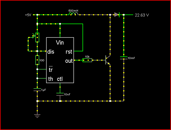
It produces between 50-100v open load (the simulation is wrong)

Here are my values

Input Voltage=5V
Transistor HFE=890
555 Output=4000hz - 50% duty
Capacitor size=1000uf 63v
Inductor size=unknown - came form a pc power supply unit
Diode =5819 schottky diode
Saturation resistor=470 ohms

If i connect a 12v PC fan to the output the voltage drops to about 7v. Why is the voltage decrease so great and is there a way to to decrease the voltage decrease?
 

Attachments

  • Capture.PNG
    Capture.PNG
    14.5 KB · Views: 848
Last edited:
An unloaded boost converter will show very high voltages and should not be used as a comparison at all. Put a 10k resistor on the output cap, which should help stabilize the "unloaded" value a bit. It will also discharge the cap so you don't zap yourself in the future.
 
ok i have added a 10k ohm resistor to my circuit. How can i boost the voltage given off when there is a heavy load attached. I want to run a computer fan off a 5v input but once a fan is connected i only get an increase of about a volt
 
What is the resistance of the unknown inductor?
 
The transistor is not a linear amplifier with a high hFE, it is used as a saturated switch with a low collector current of only 3mA because its base current is only 0.3mA.
 
To boost the voltage further, you need to increase the duty cycle of the PWM. However, be careful when it's unloaded as the voltages can spike easily.

Btw, what exactly is the source of your 5V?
 
its a DC bench power supply capable of creating 30 volts at 3 amps. I've set it too CC of 1 amp(for short circuit conditions) and CV of 5V

@audioguru sorry i did that schematic quickly. It was actually set as a 470 ohms 0.5watt resistor
 
Last edited:
The 555 has an output current of 200mA max and your 470 ohm base resistor allows a collector current of only 64mA.

Why don't you use a low value base resistor so that the transistor can have an output current that is high enough?
 
ok I have placed a 100ohm resistor as the saturation resistor. I can now get 12v from 6.5v but it still is not enough. I will be messing around with the duty cycle to see if i can get a higher voltage
 
If i connect a 12v PC fan to the output the voltage drops to about 7v. Why is the voltage decrease so great and is there a way to to decrease the voltage decrease?

Remember a typical PC fan (80 mm) at 12 volts will look to draw about 160 mA. To be on the safe side of things figure you want 12 volts @ about 200 mA available to your load. Just something to keep in mind.

Ron
 
If you want 12v at like 200mA boosted from 5v then you will need over a amp of switching current in the inductor! You should use a mosfet instead of a transistor.

-Ben
 
I have made revision to my circuit. However i am still not getting 12v. I have found an inductor with a marking of 220k so i think it is 22uH which i am now using. i have also changed the 10k resistor with a 100 ohm. The transistor i'm using is a C2335-R and the 60 ohm resistor simulates my fan. The output frequency of the 555 is approximately 20khz. What can i do to increase my output voltage further:

capture-png.50898
 

Attachments

  • Capture.PNG
    Capture.PNG
    16.8 KB · Views: 1,459
Your inductor is way out. Try one with about 470uH (471 markings) or 680uH.

Your circuit also does not have good control of duty cycle, you should use a 555 circuit that has diodes on the charge/discharge paths so you get a much better control of duty cycle.
 
The 2SC2335 is a high voltage power transistor. It saturates poorly and has low gain.
The 100 ohm base resistor provides a base current of about 28mA and the saturated collector current might be 180mA. Then the output might be only 75mA at 12V. But your 60 ohm load needs 200mA at 12V.

I don't see a part number for the diode. It should be a Schottky high speed one.
 
Hello there,

There are a couple of simple equations that are used with boost converters that can help you get to the right circuit values and settings pretty quick. The first is the calculation of the minimum inductor value, and the second is the calculation of the required duty cycle.

The minimum inductor value is based loosely on:
V=L*di/dt
which translates to:
Vin=L*imax/ton
where
Vin is the input voltage,
imax is the max current, and
ton is the 'on' time of the transistor.

The on time is determined by the frequency and duty cycle, but for a 50 percent duty cycle it will be:
ton=1/(2*f)
where f is the frequency,
and the max current is determined by either the max collector current of the transistor or the available max input current, whichever is the least.

Solving that equation:
Vin=L*imax/ton
for L gives us:
L=Vin*ton/imax
and that L is the min inductance so we'll call it Lmin:

Lmin=Vin*ton/imax

With your current setup,Vin=5 and f=20000 so ton=1/40000. imax input is 1 amp but perhaps the transistor is only 500ma, so we'll use 500ma just for now.
Using that equation we get:
Lmin=Vin*ton/imax
Lmin=5*0.000025/0.500=0.00025 or 250uH.

You can double check your actual circuit limits and recalculate if needed.


The second equation relates the duty cycle to the output voltage and is:
Vout=Vin/(1-D)
where
Vin is again the input voltage, Vout the output voltage, and D is the duty cycle expressed as a fraction (D=0.5 for a 50 percent duty cycle).
Although this equation is not exact (it will err on the low side), it does give us a quick estimate of what we might expect on the output.
For your setup, Vin=5 and D=0.5 so we get:
Vout=Vin/(1-D)
Vout=5/(1-0.5)=10 volts.
Notice that already we dont get enough output.voltage if we really want 12 volts.
To get 12v output we can solve that equation for D so we know what to set the duty cycle at:
Vout=Vin/(1-D)
D=1-Vin/Vout

Plugging in the values for Vin and Vout we get:
D=1-5/12=0.583333

so the duty cycle would have to be about 58.3 percent, but because there will be losses in the circuit we increase that a little to say 62 percent and try that. This of course means you'll have to change some of the values in your circuit or make adjustments to get the duty cycle up higher.

Also, when we calculated the min inductor value above we assumed a duty cycle of 50 percent, so now we have to recalculate the min inductor value.
With a frequency of 20kHz that gives us a period of 50us and since the duty cycle will be 62 percent the on time will now be:
ton=Tp*D
ton=50us*0.62=31us.

Going back to the equation for min inductance:
Lmin=Vin*ton/imax

now we calculate:
Lmin=Vin*ton/imax
Lmin=5*0.000031/0.500=0.000310 or 310uH.


In short, to get the required 12v output you'll have to make sure the inductance is large enough and you'll also have to make sure the duty cycle is high enough. Of course you also have to make sure that the transistor can handle the current and that its saturation voltage is low.
 
Last edited:
Thanks for your help. I will buy a 310uH inductor tomorrow. Looking at what Ben7 has said is it possible to change my transistor to a MOSFET easily. To get the more accurate frequency's I will be looking at a PIC chip to control the voltage possibly with a feedback input.

Ben7 is there also a way to make it much more efficient so i don't get so much heat output ~5 times as much current seems quite high given the calculation of:

P=I*V
P=0.2*12
P=2.4W

I=P/V
I=2.4/5
I=0.48A input in ideal conditions - I realize there will be losses but i would be loosing a lot in heat
 
The transistor or Mosfet in a boost converter operates cool because it complerely turns on hard with a very low voltage across it then it turns completely off with no current. If it switches on and off very quickly then it spends a very small amount of time with both voltage and current which causes heat.
I think you calculated how much the load will heat.
 
when i ran my circuit last it was rapidly gaining tempurature. It got very hot in less than a minute and it was using anbout 0.9A. Why could this be then?
 
0.9A from 5V is only 4.5W. The fan probably used most of it. You used the wrong transistor because it is rated for a very high voltage instead of low loss.
 
Status
Not open for further replies.

Latest threads

New Articles From Microcontroller Tips

Back
Top