Continue to Site
Follow along with the video below to see how to install our site as a web app on your home screen.
Note: This feature may not be available in some browsers.
But, to be honest, in this case, this is overkill for designing a good system. It would be enough to use the dynamic equations to make a numerical model of the system (using Matlab or Simulink for example) and manually tune your PID controller. You may even be able to estimate good PID gain values using some formulas, and then fine tune it experimentally.
") Just kidding. I will try to learn it myself too. Thanks.
Just kidding. I will try to learn it myself too. Thanks.
At this stage, it's not even clear to me what control approach you will use. Most of the guidance from your reference and from NorthGuy is saying to use a very simple direct feedback with duty cycle as the control input and P&O as the algorithm. If you do that, then control analysis is not even required, as far as I can tell.
Well, in my view, control analysis is always preferred when it can be done. This is definitely a case where doing it is very feasible, and I would do it if it were me. However, I have experience doing it, I enjoy doing it, I personally design better that way and I can do it in a reasonable amount of time. So for me, it makes sense. However, not everyone will take this path and certainly this project can be done in a common sense fashion.Yes, I intend to use direct feedback with duty cycle as the control input and P&O as the algorithm. But why isn't control analysis required in this case? Could you please tell me? Thanks.
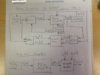
I have tried to draw a block diagram for the circuit in terms of control theory. Is it correct? Don't we need to include the buck converter too in the diagram?
I know that it's going to sound very silly and stupid but anyway I should clarify it. I was thinking that we were using a microcontroller with P&O algorithm, so what's this talk about PID controller?!
I would prefer to see a better diagram with more accurate labeling. For example, the solar input is unclear. What is that? The output of the controller, is it duty cycle? If so, label it. The system is not just a capacitor, but is an entire buck converter. What exact measurements are you taking? Show them clearly.
I understand that the diagram will likely evolve as you learn more and make decisions, but I think you can include more than what is shown, even at this point.
Seems reasonable to me. I guess hardware chips do exist, if you look for them. However, they are very simple to implement using a simple opamp circuit. Nowadays, we see more an more implementation digitally using a microprocessor.This is my understanding of PID controller. It is an algorithm, just like P&O, which is used to provide a stable relationship between an output and input by minimizing the error. That algorithm could come in a form of hardware chip as an embedded algorithm or can be implemented in software form. Kindly correct me.
Maybe I can sketch something up soon.I showed Cin as a separate system because it looked more logical and descriptive to me. We are sensing the current and voltage of Cin to drive the switching of buck converter. If you don't mind, could you show me how you would draw those diagrams because I might need to show them in next couple of days? This way I will get some time to understand them properly. Thanks a lot.
By the way, you are correct that we sense the voltage of Cin, but I believe you are not planning to sense the current of of Cin directly. You will be measuring the cell current I thought. Is that correct?
I think the capacitor C_in in Figure 2 plays the role of input voltage source for the buck converter and at the same time also functions as dummy load or resistance to the panel.
If you don't mind, could you show me how you would draw those diagrams because I might need to show them in next couple of days?
With what I showed, you could include it or not include it. I don't really see the advantage of excluding it, but certainly you can exclude it and do the charging with a separate block. If you notice, I showed a load. The battery charger circuit and battery, and the load on that system, would become the total load on this system. The diagram is quite general to handle many cases.It looks like you are also including battery charging algorithm into MPPT.
You can do that. It seems redundant and inefficient to me. Can you explain your rationale for doing this?But I wanted to design maximum power point tracker not maximum power point charge controller. I had thought of using a separate battery charging IC, like this one, to regulate the charging.
No, I think the original that I provided still holds up. The load is the battery charger as I mentioned above. The capacitor in your buck converter will still be at risk of getting overcharged, and protection against this is even more critical. In fact, now you are in a situation where you might need a faster feedback loop just to prevent the cap from blowing up. A battery charges gradually and gives you time to do a charge shutdown, but a cap charges quickly. Basically, as soon as your battery charging system fully charges the battery, it will stop charging and become an insignificant load to your buck converter. You either need to shutdown the buck converter or turn on a bleeder resistor to prevent the cap from exploding.If I exclude the battery charging part from the block diagram as I'm only trying to design a tracker, then do you find my edited version correct?
Huh? Why would you think that? The digital system is your P&O algorithm plus any other features, such as protection and shutdown. Did you suddenly decide to not implement P&O or do any control at all?Don't you think excluding the battery charging part also renders that digital system block diagram at the bottom somewhat irrelevant?
That line is labeled i_in(t) which is the input current to the buck converter. The capacitor C_in will be charged by the difference in the i_sc(t) and i_in(t) currents.What does that line running from buck converter into the Cin represent?