Electro Tech is an online community (with over 170,000 members) who enjoy talking about and building electronic circuits, projects and gadgets. To participate you need to register. Registration is free. Click here to register now.
Welcome to our site! Electro Tech is an online community (with over 170,000 members) who enjoy talking about and building electronic circuits, projects and gadgets. To participate you need to register. Registration is free. Click here to register now.
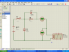
Yes, they do have back EMF. That is why the diode is required.
The diode limits the back EMF to about 0.7 Volt and therefore protects the MOSFET and the switch contacts.
If the diode was not connected, the back EMF would be very large and it would destroy the MOSFET and cause arcing across the switch contacts as they open - thus eroding the contacts.
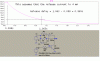
The 82 Ohm and capacitor are not shown for simplicity. But they are assumed to be connected across the relay coil as in previous diagrams.
If a resistor of 1000 Ohm was connected across the coil, the voltage across the coil at the instant the contacts open would be 20 mA * 1000 Ohm = 20 Volt.
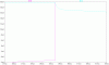
I have simulated the cases with and witout a diode across the 82 Ohm resistor. See attachments
As you can see, the release delay is slightly longer without the diode.
This is because the time constant is 600 * 1000 uF = 600 mS with the diode and (600 + 82) * 1000 = 682 mS without the diode.
Since I don't know what relay you are using, I have assumed that the relay release current is 4 mA.
No! As I told you in an earlier post, the current decays from 20 mA.
The simulations I attached earlier are attached here again.
The simulations show that the release time is a little longer without the diode. So why include a diode?
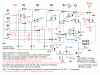
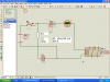
By the way, your relay contact is transposed. The N/C contact should be connected to the negative side of the battery and the N/O contact should go to the coil.
I have been reading and following the posts for this thread.
It looks as though you are not reading the EDIT's that Len is posting when he answers your questions.
I understand there is a language problem, BUT it is important that you read his replies carefully and answer his questions, so that he can help and guide you.
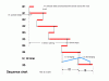
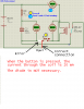
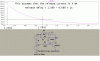
Your timing diagram is not quite right. See the attachment.
Relay X1 holds via diode D5 until B2 is released.
Relay X2 holds via diode D7 until B3 is released.
This is necessary because X2 opens the holding path of X1. So the X2 contact must hold itself before X1 releases, otherwise X2 might release when X1 releases. It depends on the operate time of X2 and the release time of X1.
I assume that X5 is a new relay. You will need it to do what you have shown in the diagram.
I will leave it to you to work out how to do it. Let me know if you need help.
I would make X4 slow release like RS and use RS to operate DS.
This site uses cookies to help personalise content, tailor your experience and to keep you logged in if you register.
By continuing to use this site, you are consenting to our use of cookies.


")