Continue to Site

Welcome to our site!

Electro Tech is an online community (with over 170,000 members) who enjoy talking about and building electronic circuits, projects and gadgets. To participate you need to register. Registration is free. Click here to register now.

  • Welcome to our site! Electro Tech is an online community (with over 170,000 members) who enjoy talking about and building electronic circuits, projects and gadgets. To participate you need to register. Registration is free. Click here to register now.

Basic problem with transistors

Status
Not open for further replies.
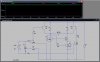
Okay I've modelled my modified version of Hero's schematic as best I can with LTSpice, but how do I monitor it using the simulation? :confused: I just get an empty graph with nothing marked on it when I try to simulate.


marcbarker said:
Maybe you could patent this?

Patent the idea of using the voltage between PA0 and PA1 to control current flow through the uC circuit rather than simply connecting straight to the uC GND? It seems unlikely that will obtain a patent... :rolleyes:
 
Last edited:
If it's still a concern, a low-dropout current limit circuit can be added to limit the current to 1 A. However, a series switch & current sense is going to be a bit tricky on 3 V, a simple fuse or PTC device (like used in cellphone battery) would probably be better.
I was going to suggest a sense resistor in series with the 0V rail and another transistor plus zener diodes to cut-off the the bases when the voltage across the sense exceeds Vbe. Then I realised that when it's short circuited the transistors would still have to dissipated 3V × Ilimit which would exceed the maximum rating of anything in a TO-92 package.

I think 1A is too high anyway, PTC resistors take awhile to act and will allow several times the rated current to pass before cutting out; a typical small transistor e.g. PN2907A has a maximum current rating of 800mA and will probably be destroyed before the polyfuse blows.

I'd recommend using a PTC rated to twice the motor current, even then this might be too much.

giftiger_wunsch,
Does your MCU have a comparator?

I have an idea that might work, you could configure it so it oscillates when the current limit is exceeded, this will prevent the transistors overheating as the duty cycle could be set low.

Look at my previous circuit.

Notice how I've implemented protection from both inputs being high by adding a zener so it shorts Tr2's base to 0V when Tr1 is activated?

Current limiting can be implemented in a similar manner.

The comparator is configured as a Schmitt trigger oscillator with R10 and C1. Normally the oscillator is inactive, when the voltage across Rs exceeds the lower threshold of the Schmitt trigger, Tr7 is turned on which connects the bases of Tr1 and Tr2 turning Tr3 to Tr6 off. With all the transistors off, C1 discharges until its voltage drops below the upper threshold of Schmitt trigger, Tr7 turns on and the cycle repeats.

This current limiter adds extra complexity but it might be worth it.
 

Attachments

  • 3V h-bridge Ilimit.GIF
    3V h-bridge Ilimit.GIF
    7.6 KB · Views: 4,149
Last edited:
Hero999, if my original idea works the way I believe it should, then it will protect the circuit against both PA0 and PA1 being high. PA0 & PA1 will use each other as a GND, so that current can only flow through the uC circuit if one is high and the other is low. If both are high, there's no voltage between them, so none of the transistors are activated.
 
You need to press the Run button, then add Probes.

Patent the idea of using the voltage between PA0 and PA1 to control current flow through the uC circuit rather than simply connecting straight to the uC GND?

No! No! The novel bit (that everyone misses) is how the uC drives the motor directly from the uC outputs as though the uC is a H-bridge itself, and it is SERVO ASSISTED!! Genius!
 
Last edited:
I haven't looked at the original circuit myself.

I don't see why it won't work. audioguru might have a point about the saturation voltage being too high at such a small base current, I trust the datasheet more than a simulator program.
 
I trust the datasheet more than a simulator program.
Yeah, remember a few years ago a "famous name" in amplifier design, he used to write for constructor magazines. When MOSFET amplifiers were getting THD performance of 0.001% according to Spice simulations, there was loads of articles published and sales of Mosfet amps increased. It later turned out that the Spice Models were faulty! the THD was really 0.003% or something.

According to the FET datasheet it's true. I've not checked the BJT D/S.
 
Last edited:
I'm not quite sure I follow. :confused:

The uC drives the motor 'directly'. Via 'power assistance' (the transistors+ 2.4V battery).

While the uC drives the motor, the greater the loading, the more current is drawn from the uC. ('force feedback')

That's what I mean by servo-assisted.

Just like a car's PAS, the motor current circuit is on a different 'mechanical system' to the uC circuit.
 
Last edited:
The greater the motor loading, the more current is drawn from the uC.

Hmm... I didn't even realise that would be the case :D


I've attached a screenshot of my attempt to adjust Hero's schematic and simulate it using LTSpice... probably unsuccessfully, on one or the other, or maybe both counts :eek:
 

Attachments

  • ltspice1.jpg
    ltspice1.jpg
    194 KB · Views: 198
I've attached a screenshot of my attempt to adjust Hero's schematic and simulate it using LTSpice... probably unsuccessfully, on one or the other, or maybe both counts :eek:

You're missing a Ground symbol. All the voltage readings have to be referenced somewhere. Some simulators even crash without a ground.

Post the ASC file here if you like.
 
And bears little resemblance to reality :D

First big mistake is the input - you're assuming high voltages and big current capacity from the source - neither are likely to be the case.
Nicads can give huge currents. I've burned myself when shorting a Nicad with a resistor leg, it got so hot it glowed red hot!
 
And bears little resemblance to reality :D

Well that is the potential problem with simulations. Unless every characteristic is specifically included, they don't simulate PCBs, stray capacitance and manufacturing tolerances. Seasoned engineers know that for a simulation to fully represent realilty, some extra components (such as capacitance, inductance etc. are added to the simulation)

So what would can you suggest please Nigel, in order to make the simulation 'closer to reality' ? :)

I'm thinking of lumped resistance inserted in the 2.4 V source, how many milliohms do you think?

Here's the .ASC file attached
 

Attachments

  • brid.asc
    2.1 KB · Views: 137
Last edited:
Nicads can give huge currents. I've burned myself when shorting a Nicad with a resistor leg, it got so hot it glowed red hot!

Yes, you could probably spot-weld things together with big nicads!

Do you think the nicad power source I simulated in brid.asc is good enough?

Anything you can think of how the simulation can be made closer to reality?

If Nigel + anyone else kindly adds whatever is needed to make the "2bjt/2fet" simulation (brid.asc) closer to reality, then what has been done here can be also applied to the hero999 circuit (sam-mp-proto3a.asc) which Giftiger is working with to improve it also. :)
 
Last edited:
Anything you can think of how the simulation can be made closer to reality?:)
The transistor with 150mA collector current and only 0.95mA base current will not saturate with only 0.14V Vce. It will have a loss of about 1V typically and might be worse.

If the base current for the transistor is increased so it can saturate with less loss then the output voltage of the resistance of the micro will have an increased voltage drop.

I don't know if the motor will start and run with only 1.2V or less.

I think the transistor should be an NPN common-emitter type driving a PNP common emitter type for plenty of current gain and low voltage loss.
 
A lot of this is going over my head so I'm going to work on drawing up my addition to hero's schematic and see how that goes. :)
 
Yes, you could probably spot-weld things together with big nicads!
That's certainly true, I've set fire to PVC cable before due to a short circuit.:eek:
 
Well that is the potential problem with simulations. Unless every characteristic is specifically included, they don't simulate PCBs, stray capacitance and manufacturing tolerances. Seasoned engineers know that for a simulation to fully represent realilty, some extra components (such as capacitance, inductance etc. are added to the simulation)

So what would can you suggest please Nigel, in order to make the simulation 'closer to reality' ? :)

I never use simulators, as you commonly have to modify circuits to make them simulate properly, I don't see as they are accurate anough for use.

I'm thinking of lumped resistance inserted in the 2.4 V source, how many milliohms do you think?

It's the input from the processor that is completely wrong, you need to add the correct voltage output and impedance to drive the H-Bridge.

Notice the commercial H-Bridge I posted earlier uses driver transistors, this allows suitable voltage and current to switch the transistors sufficiently. One crucial part for that simple design is NOT to use NICAD's, as it relies on the internal resistance of the batteries to limit current to the motors. In simple tests I did (using a PJ996 battery) the motor took over 6A when stalled - and I'm pretty sure that was limited by the battery, NICAD's would be MUCH higher.
 
So now it appears I'll need a way of limiting this current so that it doesn't draw a massive current while the motor is stalled, which could potentially damage both the transistors and the battery... I've used up all of my fingers and toes counting all of the problems that have been spawned by this 'basic' problem :eek:
 
Status
Not open for further replies.

Latest threads

New Articles From Microcontroller Tips

Back
Top