What? When did the circuit have 3 batteries? And why would it only get 1.2V?
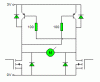
Feeding the motor from the emitters of the transistors is the worst possible method, and will lose you the most voltage possible - using only a 3V supply to power an h-bridge is really far too low, you will lose more then the motor gets.
") ). It's been mentioned that 3V motors can typically be used at much higher voltages, and making the supply 3.6 - 4.8V should account for some of the voltage losses.
). It's been mentioned that 3V motors can typically be used at much higher voltages, and making the supply 3.6 - 4.8V should account for some of the voltage losses.