Continue to Site

Welcome to our site!

Electro Tech is an online community (with over 170,000 members) who enjoy talking about and building electronic circuits, projects and gadgets. To participate you need to register. Registration is free. Click here to register now.

  • Welcome to our site! Electro Tech is an online community (with over 170,000 members) who enjoy talking about and building electronic circuits, projects and gadgets. To participate you need to register. Registration is free. Click here to register now.

Audio help needed.

Status
Not open for further replies.

fingaz

Member
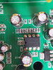
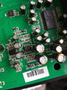
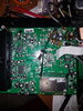
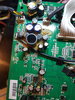
I'm trying to repair a stereo system it's a Roberts mp-sound 43.
It basically sounds very distorted at all volume levels but worse the louder it gets. Sounds very bass. It's based on JRC NJM2706 and ET2314. It worked fine, went into storage for about 6 months, now sounds awful.
Strange thing is that through headphones it sounds fine with no distortion.
Datasheets for the 2 chips attached.

Any suggestions or help would be greatly appreciated.
 

Attachments

  • ET2314.pdf
    559.6 KB · Views: 463
  • datasheet.pdf
    217.8 KB · Views: 201
For a start I'd try a different pair of speakers on it - headphones are very often fed from the speaker outputs anyway (via attenuators).

But unfortunately Roberts these days is just cheap Chinese imports with a big price tag, and little in the way of spares or service information. I used to work for a Roberts dealer.

If you go to the Middle East you can often buy identical looking products with different names on the them, at about 1/4 of the price.
 
I should have said, I did try a different set of speakers with the same outcome.
 
Can't find a service manual on it, but this type of problem is almost always related to the amplifier output sections - either a failed output transistor or a bad speaker relay (if it has one). The output stage is able to supply enough current for headphones, but not enough for speakers.
 
These are the only audio related chips o the board. It's only 10w output into 8 ohm speakers.
 

Attachments

  • 20210216_154135.jpg
    20210216_154135.jpg
    1.5 MB · Views: 214
  • 20210216_154217.jpg
    20210216_154217.jpg
    1.8 MB · Views: 209
Can't find a service manual on it, but this type of problem is almost always related to the amplifier output sections

Unfortunately Roberts have long since stopped supplying manuals and spares.

They were never highly thought of anyway, always just the poor man's Hacker :D
 
Neither of the two chips you listed are power amplifiers.

Here is the whole board. The chip at the bottom right is tda2822, to the left of that ET2314, to the left of that NJM2706. As I said, its low power.

The TDA2822 is not faulty, already tried replacing it.
I should say that with the left speaker disconnected, there is not sound distortion. It appears to be only on the left channel.
 

Attachments

  • 20210216_193322.jpg
    20210216_193322.jpg
    2.7 MB · Views: 207
Last edited:
Here is the whole board. The chip at the bottom right is tda2822, to the left of that ET2314, to the left of that NJM2706. As I said, its low power.

The TDA2822 is not faulty, already tried replacing it.
I should say that with the left speaker disconnected, there is not sound distortion. It appears to be only on the left channel.

The TDA2822 is a low power audio amplifier, and presumably feeds the headphones?.

From that picture I would suggest the power amplifiers are at the top right of the PCB, possibly on the other side of the board?.
 
Can you determine where the wires from the speakers connect to the board? Closer view of that part of the board?
The TDA2822 is a low power audio amplifier, and presumably feeds the headphones?.
Could be, but a separate amp for the 'phones is not a hallmark of cheap amplifiers.
 
Can you determine where the wires from the speakers connect to the board? Closer view of that part of the board?
Could be, but a separate amp for the 'phones is not a hallmark of cheap amplifiers.

There's probably a good reason it's done that way - it's quite common in TV's, when you find a TV with a headphone socket.
 
The TDA2822 is a low power audio amplifier, and presumably feeds the headphones?.

From that picture I would suggest the power amplifiers are at the top right of the PCB, possibly on the other side of the board?.
Nothing on the underside of the board.
 
Can you determine where the wires from the speakers connect to the board? Closer view of that part of the board?
Could be, but a separate amp for the 'phones is not a hallmark of cheap amplifiers.
Yellow/black/red to the left is for left speaker.
White/black/red to the right is for right speaker.
 

Attachments

  • 16135064929647149135452101515435.jpg
    16135064929647149135452101515435.jpg
    2.2 MB · Views: 202
This may now be a lost cause. The left speaker is not giving any output now.
 
Yellow/black/red to the left is for left speaker.
White/black/red to the right is for right speaker.

Like I said, top right of the previous picture, some of the components round there are the low-pass filters for the class-D amplifiers.

The amp could even be the small SM transistors nearby.
 
Like I said, top right of the previous picture, some of the components round there are the low-pass filters for the class-D amplifiers.

The amp could even be the small SM transistors nearby.
Yeah, I think I'll leave it at that. I'm not messing around trying to identify SMD transistors. Not to mention there's a lot of glue on the board there covering a lot of the SMD components.
I wanted to try to get it working for the challenge, but it doesn't seem worth the effort now.
Thanks for the input
 
Like I said, top right of the previous picture, some of the components round there are the low-pass filters for the class-D amplifiers.

The amp could even be the small SM transistors nearby.
I agree it's the top right - but I suspect there is an IC on top of the board, with that tubular looking object on the top of it; right in the centre of the glue area.

Note the custer of parallel tracks heading under the glue from the left - to IC pins nearby??
 
I agree it's the top right - but I suspect there is an IC on top of the board, with that tubular looking object on the top of it; right in the centre of the glue area.

Note the custer of parallel tracks heading under the glue from the left - to IC pins nearby??
I may have another look around that if I can get all the glue off.
 
Status
Not open for further replies.

Latest threads

Back
Top