Continue to Site

Welcome to our site!

Electro Tech is an online community (with over 170,000 members) who enjoy talking about and building electronic circuits, projects and gadgets. To participate you need to register. Registration is free. Click here to register now.

  • Welcome to our site! Electro Tech is an online community (with over 170,000 members) who enjoy talking about and building electronic circuits, projects and gadgets. To participate you need to register. Registration is free. Click here to register now.

Audio Amp output?

Status
Not open for further replies.

jrz126

Active Member
As most of us know, the equation P=V*I doesnt apply to audio amps (especially car audio). It seems like most of the ratings for amps are usually inflated quite a bit.

I'd like to try to measure the output of my amp. It's a Hifonics 1000W class D amp. which is supposedly able to put out 1000Wrms at 1 ohm. Now what I'd like to do is to use my oscilloscope to try to measure the power coming out of the amp.
I recently got ahold of some 12 ohm 200W resistors that I was going to use as my load. They have a center tap so they are basically 2 6 ohm resistors. I'm going to use 6 of the 6 ohm resistors to get my 1 ohm load. My subs are only rated for 800W rms, so I dont want to risk blowing them.

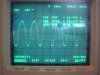
So I already tried connecting this resistor set up, but when I go to connect my o-scope leads, the amp starts clicking pretty fast (I think it's going into protect mode?). this kinda puzzled me as to why this would happen. The more confusing part is that I'm able to see the sine wave on my scope with just the probe lead connected (no ground). So I only have one wire connected to the amp, how can it complete the circuit?

ok, this post is long enough, so does this sound like it will work? what kind of effect will the resistors have on my results?
 
Hi Jeff,
Don't use a sine-wave to test the amp. Its cooling is probably only made for music, that has a duty-cycle making 1/10th the average power.

Maybe you are connecting the ground terminal of your 'scope to one of its speaker wires. It is probably bridged, so both wires are live. Connect the 'scope's ground to the amp's ground, and a hot channel input of your 'scope to each speaker wire. The signals will be out-of-phase and you can measure peak-to-peak.

What are you supplying the amp with? A 12V car battery will have a 100A current and you could lose hundreds of watts in the connections and wiring.
 
As someone who's built and repaired many amplifiers over many years, I wouldn't attempt to power test into a one ohm load!.

Rewire your loads to give either 8 ohms or 4 ohms, then do the tests - 8 ohms is preferred, as I very much doubt the amplifiers capability into low impedance loads.

As Audioguru says, the spec of the amp almost certainly won't handle sinewaves - which means you can't get a meaningful measurement out of it. Perhaps you may be able to with only an 8 ohm load, which is why I suggested 8 ohms rather than 4 ohms.

A poor quality amplifier has a much larger chance of failing during power tests, so keep them VERY short! - and don't be too surprised if you hear a loud bang, and see clouds of smoke :lol:

As Audioguru also said, you need to be aware of the high current requirements - they will be extremely high, requiring a big battery and very thich, very short, leads.
 
The amp can handle a 1 ohm load, Thats the reason I got this amp. I have 2 12" kicker CVR's with dual 4 ohm coils, which gives me 1 ohm.
https://www.maxxsonics.com/hifonics/ampsnew_brutusSpecs.html I'll probably rewire my load resistors to 3 ohms or something.

As for the power wire, I've got a 4 gauge wire, and it's about a 20 foot run from the battery to the amp.

So what waveform should I use?

Also, I only have 1 probe, so does that mean I connect it to one of the wires and amp ground and just double my answer?
 
Yeah Jeff,
He, he. Don't do your test until I get there. I want to see the big Ka-Boom! :lol:
 
Hi again,
A 3 ohm load is more realistic for testing. If the amp survives, you can try it with only 1 ohm. You will lose a lot of power in a total of 40 feet of power supply wiring!
I would test it with FM music. It is highly compressed so its max level is always the same. Connect your 'scope to one speaker wire and the amp's ground. Turn up the volume until it smokes or you see clipping. Measure and record the peak voltage seen on the 'scope. Measure the other speaker wire. Its peak reading should be the same. You're correct, just add the two for p-p.
 
audioguru said:
Hi again,
A 3 ohm load is more realistic for testing. If the amp survives, you can try it with only 1 ohm. You will lose a lot of power in a total of 40 feet of power supply wiring!
I would test it with FM music. It is highly compressed so its max level is always the same. Connect your 'scope to one speaker wire and the amp's ground. Turn up the volume until it smokes or you see clipping. Measure and record the peak voltage seen on the 'scope. Measure the other speaker wire. Its peak reading should be the same. You're correct, just add the two for p-p.

Just double the single peak reading, it's going to be identical to the other one - certainly far more so than you can distinguish on a scope!. If you're running the amp at the threshold of clipping you don't want to keep it there for any longer than the possible minimum!.

However, taking the peak reading on a music signal doesn't give you an RMS output, or any really quantifiable result - but at least it'll give you some indication of the output.

I checked the specs on the Hifonics site, it doesn't appear to suggest the claimed output is RMS?, or indeed give any indication of what it might be?. In-car amps commonly make wildly exaggerated output claims, I see no reason to suspect these are any different? - this isn't to say I'm not impressed by what performance they DO offer!.
 
Yeah, I didn't look at the amp's "spec's" until now. Its output isn't even rated in Watts, maybe only mW or just ordinary Whats!
It is probably rated in "peak music power", which is double its RMS rating and measured just before its power supply voltage sags.
Does it have only a 5A fuse?
 
Nigel,
Don't worry about car amps blowing up from clipping with music. Car guys play them clipped all the time. It is so loud in their cars that only people outside can hear how distorted they are!
Besides, the speaker voice coils and wiring heat-up and increase their resistance, and the resulting "power compression" protects the amps somewhat. :lol:
 
First off, I've got a 3 ft section of 4 gauge grounded to the chasis for the ground. so it isnt straight 40 feet of wire for the whole circuit.

It is probably rated in "peak music power", which is double its RMS rating and measured just before its power supply voltage sags.
Does it have only a 5A fuse?

this amp isnt the cheepo crap that is out there. When I had my ported box in there **broken link removed**
It was enough bass to make my chest hurt, so it's definitly more than 200W.

As for the 1000W rms or peak, Thats partly what I'm trying to figure out, some people say rms others say peak.
 
jrz126 said:
this amp isnt the cheepo crap that is out there. When I had my ported box in there It was enough bass to make my chest hurt, so it's definitly more than 200W.

A genuine 200W in a space that small, through anything approaching a 'decent' speaker, would be far above the threashold of pain, and possibly cause bleeding from the ears :lol:

As for the 1000W rms or peak, Thats partly what I'm trying to figure out, some people say rms others say peak.

If it doesn't state RMS in the specs, it's going to some imaginary rating which you won't be able to duplicate! - for your in-car system, it doesn't really matter, as everybody elses system has the same imaginary power ratings.

RMS power is going to be at least half the rated power, and I've seen specs in the past (where they gave both values) where the RMS power is only a quarter of the rated output!.

To test the RMS power output you need to drive it from a sinewave, I would strongly suggest you do it with no lower than a 4 ohm load - the amp spec says 350W at that impedance. I would suggest you're probably looking at 175W RMS or so? - this will be about 74V p-p. As it's a bridged amplifier, the output from one pin should be 37V p-p.

There's no guarantee that a test like this won't kill the amplifier - PROCEED AT YOUR OWN RISK!.
 
My plan is to just increase the volume until the sine wave starts clipping. is this correct? When they rate the amps output, is this what they look for?
 
jrz126 said:
I've got a 3 ft section of 4 gauge grounded to the chasis for the ground.
The car's chassis is steel which is a poor conductor. You'll be lucky to get 9V back there if the amp tries to produce 1000W. Don't the tail lights flicker to the beat? I've seen it.

I had my ported box in there.
I see it is a nice big one. Where do you carry groceries?
I know, you carry them on top of the car so they don't get squashed by the sound! :lol:
 
Hi Jeff,
Car amps usually have their power ratings at 10% distortion which is badly clipped, sounds horrible and makes the numbers about 25% higher.
The power output of a "real" amp is measured just below clipping.

I see smoke on the horizon, is it your amp? He he. :lol:
 
Well I got some results: sorry about the glare, and picture size, my
MS paint program was deleted somehow.

I believe that is reading 35.2V P-P. So that's pretty close to what you were saying Nigel.

Is there a typical test frequency that they would use?
 

Attachments

  • scope_4_ohm_30_hz.jpg
    scope_4_ohm_30_hz.jpg
    89.5 KB · Views: 1,380
Hi Jeff,
It looks awfully distorted. All the bridged amps I've seen have a symmetrical waveform on each wire. Yours is badly off-center.

Hey, your load isn't from one wire to ground, is it? That's where your 'scope probe should be. The amp's load should be connected between each output connector like a speaker.

If the load wasn't connected where it is supposed to be, the measurement doesn't mean anything.
 
jrz126 said:
Well I got some results: sorry about the glare, and picture size, my
MS paint program was deleted somehow.

I believe that is reading 35.2V P-P. So that's pretty close to what you were saying Nigel.

It was just simple maths :oops:

So that makes your amplifier look like 500W RMS in to 1 ohm, based on 175W RMS in to 4 ohms.

Is there a typical test frequency that they would use?

Usually 1KHz, or for a 'proper' test, use spot frequencies through out the audio band. As your amp is being used as a sub-woofer, using 30Hz sounds a reasonable frequency to use - personally I'd have 'chickened out' and used 1KHz though :D

Don't worry about the link from 'David Bridgen', it's a common 'attack' on RMS power measurements - basically on the semantics of the term, rather than it's practical usage - an interesting read though!.
 
Well I did some more messing around. I set my scope to DC coupling and turned the volume all the way down on the cd player. There is a 24VDC offset with my probe connected to either of the speaker terminals and ground.
whats up with that?

maybe this is why the wavefrom is funny looking?

I'm gonna try to isolate my scope from the amp by using a small transformer.

Also, the amp is only 1 channel, so there really isnt anything to 'bridge'.
 
Status
Not open for further replies.

New Articles From Microcontroller Tips

Back
Top