Electro Tech is an online community (with over 170,000 members) who enjoy talking about and building electronic circuits, projects and gadgets. To participate you need to register. Registration is free. Click here to register now.
Welcome to our site! Electro Tech is an online community (with over 170,000 members) who enjoy talking about and building electronic circuits, projects and gadgets. To participate you need to register. Registration is free. Click here to register now.
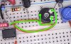
No, it only looks that way on the picture (above, you cant see the pins). The pins on my "mickey mouse breadboard" are at separate rows, on pin is bent and placed alone in its own row. I can take a picture later to show you if you want.
Thanks anyway!
(Should have rotate it 90 degrees instead of bending the pin)
Is it wrong connected like its shown in the picture?
It is not a problem Rorut- you are the one doing the work and have the patience.
My post was not clear the resistor should have been 470 Ohms.
Otherwise all is correct and the opamps are not oscillating.
Can you try again with 470 Ohms and if the reading on your meter is still essentially zero volts, the opamps are not oscillating.
With the resistor, diode, capacitor and meter connected to one of the opamp outputs, can you then inject a signal into the inputs of the opamp and see if you get a DC reading on the multimeter which varies with the input signal amplitude.
No, it only looks that way on the picture (above, you cant see the pins). The pins on my "mickey mouse breadboard" are at separate rows, on pin is bent and placed alone in its own row. I can take a picture later to show you if you want.
Thanks anyway!
(Should have rotate it 90 degrees instead of bending the pin)
Is it wrong connected like its shown in the picture?
Hi again,
Some more tests.
470ohm to anod on diode, cathode to 100nF (Film) capacitor, capacitor to ground and other end of 470 to pin 1 gives now 5.8v across the 100nF capacitor when pin 6 and 7 is connected and pin 5 to ground.
Connecting the siren with above setup gives 8.7v on multimeter.
Resistors are measured and gives correct values.
Is it oscillating now? And is that why the gain pot is not working? What is happening when the circuit oscillate?
Yes, all things being equal, that is a clear sign that the A opamp is oscillating.
If this is true it will explain the problem including the odd audio sound.
I will have a think about the best next move.
In the meantime, can you:
(1) remove all inputs and outputs
(2) connect the high frequency detector to the output of opamp A.
(3) Check that there is a reading on the voltmeter.
(4) Without shorting anything, put your finger on various points on the circuit and see if the reading drops to 0V
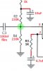
From your video it appears that the opamp is oscillating (5V approx on the HF detector) but when you touch the junction of the two 220K resistors, the HF detector shows OV.
Once again that is a classic sign of oscillations.
Can you change both 220K resistors to 22K and see if the oscillation persists.
If that does not work, still keep the 22K resistors but also fit a 100pF capacitor between the non-inverting input and 0V.
If that does not work connect a 100pF capacitor between the two inputs of opamp A.
(1) remove the 100K gain potentiometer and all associated wiring.
(2) fit a 22K resistor in place of the 100K potentiometer, but make the leads on the 22K resistor short and fit the 22K resistor as close to opamp A pins as possible. Especially keep the wires to opamp A inverting input short and compact.
Incidentally, the voltage gain of your amplifier is 1 + R2/R1 where R1 is the 1K resistor and R2 is the value that the 100K potentiometer is set to.
So with the 22K resistor fitted in place of the 100K potentiometer the voltage gain of opamp A will be 23.
I removed pot and wiring and placed a 20K from pin 1 to 1Uf and now multimeter reads 10.5v and does not go down to 0v like before when I touch the 20K (or 220K) resistors connected. Is this a good sign?
I removed pot and wiring and placed a 20K from pin 1 to 1Uf and now multimeter reads 10.5v and does not go down to 0v like before when I touch the 20K (or 220K) resistors connected. Is this a good sign?
Yes unbelievable, but I think Im learning som stuff on the way and that is pushing me forward. I bought it here: https://www.electrokit.com/en/lm358an.43035
Well known supplyer in Sweden.
Thank you!
Yes unbelievable, but I think Im learning som stuff on the way and that is pushing me forward. I bought it here: https://www.electrokit.com/en/lm358an.43035
Well known supplyer in Sweden.
Thank you!
That looks like a good source.
This is just a thought, but I have known faulty batches of components, but I do not think that is the problem.
Do you have two power supplies to give plus and minus 12V or 9V say (the supplies do not have to be the same)? a couple of batteries would do.
I am still suspicious of the 3.3uF capacitor that connects to the 1K resistor. Can you try replacing that capacitor for a non-electrolytic type, as big a value as you have- ceramic will do.
This site uses cookies to help personalise content, tailor your experience and to keep you logged in if you register.
By continuing to use this site, you are consenting to our use of cookies.