Continue to Site

Welcome to our site!

Electro Tech is an online community (with over 170,000 members) who enjoy talking about and building electronic circuits, projects and gadgets. To participate you need to register. Registration is free. Click here to register now.

  • Welcome to our site! Electro Tech is an online community (with over 170,000 members) who enjoy talking about and building electronic circuits, projects and gadgets. To participate you need to register. Registration is free. Click here to register now.

Adding a ring light to a 1981 Draper Tools PD-16 'Drilling Machine' 1981 Mascot Tools (Floor Standing Pillar Drill)

TheJay

Member
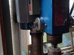
Hey everyone, I have a very old pillar drill press from 1981 (Draper). It has a green on and red off button on the side. I wondered how I can take power from the drill press when the green/black button is pressed and turn it off when the red button is pressed?

images


Even better, how could I connect a three way switch so that I can turn it on and off manually, as well as having a position for automatic.
 
This one is 11.5cm ID 12.3cm. The tang would need to be the same dimensions as the one you made. Would you mind helping me with this? Thanks.
If you mean "Can I machine another one please?" Sorry but I am not in a position to do any machining at the moment.

Can you:
1 Mark out the shape on a sheet of aluminium.
2 Chain-drill the outline and circular cut-out, using your pillar drill.
3 Use hand tools (files etc) to give a smooth shape to the chain-drilled surfaces.
4 Assemble the light and supports as appropriate using local materials.

JimB
 
For the machine start/stop, look for a "no volt release" switch on ebay. There are various styles, either surface mounted or through panel.
A couple of styles:


Add a separate (AC power rated) light switch, either a simple on-off and taking power from the motor side connector, or a three way selector switch, with centre off, one way taking power from the motor side and the other way taking power before the motor switch.
eg.
 
Thanks for your replies.

I've ordered the first NVR you linked. Thinking of mounting it facing forward on the left side of the machine like this:

images (1).jpg


Would this work as a three way switch? https://www.ebay.co.uk/itm/254230122628

Can't use the drill at the moment, it's in parts whilst I work on it:

AQyPew8[1].jpg


What was the thickness of aluminium you used?

I want to tidy it up, is there a way to reduce the size of the stuff that goes from mains to the motor/switch? What's this part called/do they make them smaller now?

image_2024-04-22_193937061.png
 
That's a motor overload thermal trip and a power contactor. The start-stop switch assembly effectively replaces the contactor - but that has no motor protection.

A motor rated thermal-magnetic double pole circuit breaker should be suitable protection for the motor.

This is an example of that type; it has a similar adjustment range to the original, which appears to be set at approximately 3A. Note that motor protection types are not the same as general MCBs used in distribution boards etc.


They have a slow reaction to minor overloads, but very fast reaction to high current overloads.

It could be connected at the machine, or at the wall plug end, depending on which is most convenient.
 
Thanks, that's really good to know. How are those mounted/are there small enclosures available/ways to make IP65 compatible?

In terms of wiring, would the idea be to go to a trip, then the NVR and from there the motor and LED light/three way switch? What would be the best gauge of cable for everything after the mains cable?
 
Last edited:
Thanks for your reply. Does that mean 1.5mm twin cable?

That source is for companies only, I am unable to order from there. Unless someone is able to order for me and I reimburse you? Do the company also provide an enclosure for this specific Motor Protection Circuit Breaker?

Would this be sufficient? It's actually quite hard to find something similar elsewhere. This looks like it's probably larger and it's 3P rather than 2P?

 
Last edited:
Yes, that would be fine (the 2.5 - 4A one).

Loop one wire out & back to the third input then out of that third way, so all sections are passing the same current; they monitor imbalance between the phases so leaving one out will cause a trip.
 
For safety reasons, you should also include a floor-mounted kill switch for the drill in case of injury by the work or you fall down during work and no one can hear your calls for help with a running drill.
I worked on a senior's home project last year having pull cords attached to the emergency call buttons, that reach down to the floor.
 
I wanted a discreet foot kill switch but it looks like the options are expensive.

Thanks rjenkins, I am waiting for bits to arrive and then will take a look/come back with a photo of the components so a diagram can be added.
 

Latest threads

New Articles From Microcontroller Tips

Back
Top