Continue to Site

Welcome to our site!

Electro Tech is an online community (with over 170,000 members) who enjoy talking about and building electronic circuits, projects and gadgets. To participate you need to register. Registration is free. Click here to register now.

  • Welcome to our site! Electro Tech is an online community (with over 170,000 members) who enjoy talking about and building electronic circuits, projects and gadgets. To participate you need to register. Registration is free. Click here to register now.

Active vs Passive Hi Pass Filter for Audio

Status
Not open for further replies.
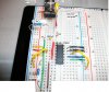
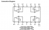
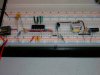
OK I missed that point. So the Op Amp has its own power supply with connectivity via + - markings near center of diagram? I assume then the unused grounds go to separate supply as well. Right now the circuit sits on a solder-less breadboard with one 9V power supply. The input is audio apx 600mV and output is a transformer apx 7:1 winding ratio that outputs to electrodes. I've tried to measure impedance of transformer and I was getting reading of around 100Ω.
 
The connection between the two batteries is the "ground reference" for the audio input/output. It is possible to transform the circuit to make it run on a single supply, at the expense of more complexity. Read this sticky.

The transformer will have a much higher impedance at audio frequencies than what you would measure as the DC resistance of the transformer primary winding using an Ohmmeter, so that should be ok. Try scoping the output pin of the opamp both with and without the transformer connected.
When you add the second battery, the other end of the transformer winding should be connected to the tap between the two batteries, too.
 
Well, I'm in a bit of a quandry: I tried my best to follow the 2pole MFB High Pass design, but was getting a low signal. The 9V single source I was using measured 6.7V with multimeter. Before trying to add a second power source, as suggested, I tried a fresh(9.4V) and the OpAmp heated up tremendously within seconds(my olfactory has become well acustomed to the scent of fried semicondutors). Strangely, the 6.7V was not producing any heat in the OpAmp. I thought it best to stop and upload a photo of the circuit, that I thought I correctly configured according to Chebychev design.
 

Attachments

  • OpAmp1.jpg
    OpAmp1.jpg
    589.5 KB · Views: 196
Pin 4 of the opamp should be connected to the positive pole of the first 9V battery, while pin 11 should be connected to the negative pole of the second 9V battery.

Connect the negative pole of the first battery to audio ground, connect the positive pole of the second battery to audio ground.

You probably cooked the opamp, as you appear to have the single battery connected backwards.
 

Attachments

  • LME.png
    LME.png
    28.7 KB · Views: 188
In the meantime, I'd like to build a passive hi pass filter using the utility on Butterworth Tee LC High Pass Filter Calculator -which calculates cap/inductor ratings for given frequency. Incidentally, why does every text book example of high/low pass show Resistor/Cap configuration, when in reality inductor/cap combinations are the only thing I've gotten to work? The RC combinations I've tried simply attenuate entire audio signal. That being stated, the above reference site has a field 'number or components'. This seems arbitrary; what would be the optimal number of components for a 17KHz hi pass? When I built the passive low pass filter(https://www.electro-tech-online.com/attachments/200_hz_lowpass-jpg.3678/), the schematic called for 4 caps and 3 inductors. Given the proper values, could I simply reverse the order for hi pass?
 
Generally, at audio frequencies, active filters are much easier to get working than dicking with inductors. Where do you buy a 3.57 mH inductor, for example.

Inductors don't have power pins, however. :D
 
Last edited:
In the meantime, I'd like to build a passive hi pass filter using the utility on Butterworth Tee LC High Pass Filter Calculator -which calculates cap/inductor ratings for given frequency. Incidentally, why does every text book example of high/low pass show Resistor/Cap configuration, when in reality inductor/cap combinations are the only thing I've gotten to work? The RC combinations I've tried simply attenuate entire audio signal. That being stated, the above reference site has a field 'number or components'. This seems arbitrary; what would be the optimal number of components for a 17KHz hi pass? When I built the passive low pass filter(https://www.electro-tech-online.com/attachments/200_hz_lowpass-jpg.3678/), the schematic called for 4 caps and 3 inductors. Given the proper values, could I simply reverse the order for hi pass?
Passive RC combinations work, they just don't work as well as an LC or Active RC filters.(Passive RCs have slower rolloff)

The number of components is not arbitrary, it determines the steepness of the rolloff outside the passband. Every LC pair will increase the rolloff by 12dB/octave in a properly designed filter. So the "optimal number" depends upon how rapid a rolloff you want.

You could reverse the L and Cs to get a high pass, but I'm not sure how well that works.
 
Last edited:
Passive RC combinations work, they just don't work as well as an LC or Active RC filters.(Passive RCs have slower rolloff)
Ok, I see.

As far as 3.57 mH, there is a place in Nashville called Randolph and Rice and they may carry it. If not them, Mouser'll have them for sure.
 
Well the hi pass works wonderfully. I tweaked a cap placement, hooked the batteries according to ML's instruction and nothing but 18K+ passes. Very cool! So now I have low, hi and all-pass designs and I'm going to construct a circuit with switching buttons to toggle between them. I suppose this is fodder for a brand new post. Thanks for all the prudent advice.
 
MikeML-am trying to boost op amp output by 1 V(PP). In current design, the output voltage sometimes dips below .6V threshold and not every pulse is being picked up by transistor. Using the filter pro software, I cannot replicate component specs in Chevychase:) design you provided-most are within ballpark but 82.5Kohm resistor is significantly higher than anything filter pro suggests. What is the PSpice version/name-I think I should acquire it?
 

Attachments

  • Circuit1.jpg
    Circuit1.jpg
    1.1 MB · Views: 193
Last edited:
You never answered to my satisfaction what the filter is driving. I dont have the time or patience to try to trace out the schematic from your photo. Post a schematic.

If you need to raise the gain, then leave the filter alone, and use one of the unused opamp sections to create the extra gain. I'm still puzzled why you need a transfromer; you never explained that, you never explained how it is connected to the output of the opamp.
 
Last edited:
Ok. I'll continue in this thread.(I thought if the functionality inquiry changed, ie transformer issue, then start a new thread).

Outputting from op amp is an AC signal apx 18KHz ranging .5V-1.2V into transistor which inverts and ups the voltage to 7V. It then goes into left primary of transformer(right primary is DC 6V). The transformer is used to step up voltage to electrodes which will be connected to skin. Sort of like feeling the music. Without transformer the voltage is too low. I will draft a schematic this afternoon.
 
It is extremely dangerous to zap people with a high voltage. Some people have a weak heart that might be stopped or they might have an epileptic fit.
Some people have dry skin and will not be affected but other people sweat and conduct a high current that might kill them.
I don't think your circuit limits the current to a safer amount.

Why are you putting DC into a transformer winding? A transformer is used with AC, never with DC. DC might cause the core to saturate then it is not a transformer anymore, it is just a piece of wire.
 
Well, I'll put in appropriate resistance such that it outputs 40mA tops. AND it's only for my use, I'm not strapping this up to folks. An experimental idea that's all. But from o-scope readings, it shows a commercial unit as having DC current of 5V on one side of transformer and AC 6V on other. I cannot replicate this functionality; the DC simply creeps onto both sides of transformer. Any idea as to how the commercial unit's transformer holds each signal independently?
 
Only people who know nothing about electronics put DC on a transformer winding.
Lots of commercial products are designed by idiots.
 
You can have DC on one side of a transformer primary if the other side of the primary is periodically switched to ground, which forms a flyback type inverter circuit. That type of inverter is typically used to achieve high secondary voltages.
 
Without a schematic then we are just guessing but it sounds like one winding has DC all the time which is not proper.
Then a second winding has AC audio.
 
Status
Not open for further replies.

Latest threads

New Articles From Microcontroller Tips

Back
Top