Jon Wilder
Active Member
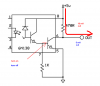
I've seen the 6N138 optoisolator hooked up a few different ways. One of them being the method shown below -
**broken link removed**
I can see where the 1K limits emitter base current to the phototransistor, but if I'm looking at this correctly there doesn't appear to be anything limiting the emitter base current of the 2nd transistor. Yet I've seen it hooked up in this configuration with no limiting resistor between pin 8 and the + rail.
Is this acceptable to do? If so, is it because the 2nd transistor doesn't have a constant duty cycle? What is the advantage to hooking it up this way as opposed to leaving pin 7 disconnected and placing a limiting resistor between pin 8 and the rail?
**broken link removed**
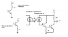
I can see where the 1K limits emitter base current to the phototransistor, but if I'm looking at this correctly there doesn't appear to be anything limiting the emitter base current of the 2nd transistor. Yet I've seen it hooked up in this configuration with no limiting resistor between pin 8 and the + rail.
Is this acceptable to do? If so, is it because the 2nd transistor doesn't have a constant duty cycle? What is the advantage to hooking it up this way as opposed to leaving pin 7 disconnected and placing a limiting resistor between pin 8 and the rail?
Last edited: