Continue to Site
Follow along with the video below to see how to install our site as a web app on your home screen.
Note: This feature may not be available in some browsers.
Colin, why did you change your name?The circuit won't work.
Mike.
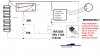
YES!!!, THIS CIRCUIT WILL WORK! at 42 volt on the battery, you will have 1/3 of that voltage on the gate, 14 V , as you battery discharges down to 36 V you still have 12 volts on the gate, at 30 volts, that's 10 volts on the gate, if you use a 15K instead of 20K, you'll have more to the gate, I thought about a zener, but I don't think that's a good idea for when you need to turn the fet off. If your bike is brushless, you may not need the diode, I can't speak to what kick back you get from brushless motors or what type of regeneration they produce, if any. Brushed permanent magnet would regenerate and the diode would cause it to brake, it's there to shunt the transient voltages and protect the rest of the circuit2.added to your schematic, one IRF3205 110 amp 55 volt FET should handle your load, voltage divider will spread the load over the whole battery stack. If your equipment has an adequate piece of metal to be a heat sink, you can mount the FET to that and insulate it if needed or mount to FET to a store bought heat sink or use piece of aluminum plate, I use alum channel fairly often.View attachment 100997 here's an example of using a piece of alum channel as heat sink and conductor that is isolated from the body of my vehicle.View attachment 100996
the diode across the motor is for transient voltages
you will also need this or similar
**broken link removed**
ebay to220 insolator
and just WHY won't this work? How much real experience do you have using high current FETs? I've been playing with IRF3205 fets for a couple of years now.The circuit won't work.
Mike.
Thank you Kinarfi, I will try this circuit for sure, I am gonna order the component´s.and just WHY won't this work? How much real experience do you have using high current FETs? I've been playing with IRF3205 fets for a couple of years now.
SimonTHK, one problem I forsee is lack of any throttle, as drawn, it's all or nothing, unless there are things you have divulged.
My son has a 24v scooter for his kids and someone took the controller out, so we had to make another


The battery is not a NIMH battery, it is lifepo4 and may never get lower than 33,6v. Which is why there are placed an intelligent control board on each individual cell, that will send information to the mainboard that if any cell gets below 2,8v (33,6v on the whole pac)k, it will turn off the latching relay, which turn of the mosfet, which turn of the LOAD, which turn off the discharging of the battery. Which is also why anything I put on this battery before the mosfet, should draw a minimum of power.kinarfi
I mistakenly thought that the gate voltage was 6.2V. However, working with 42V, at what point will the mosfet turn off? It's guaranteed to fully turn off at Gv = 2V (Battery = 6V!!). However, what about when the battery is at 13.5V and gate at 4.5V. Referring to the chart above (from datasheet) the current will have dropped to about 8A and the voltage across the mosfet will be 10 - 20V. That's 80-160W and that is enough to melt the mosfet.
I would be very interested to see your calculations.
Mike.
Seems we posted at the same time. Not knowing what a charge controller did I could only work with what I had.The battery is not a NIMH battery, it is lifepo4 and may never get lower than 33,6v. Which is why there are placed an intelligent control board on each individual cell, that will send information to the mainboard that if any cell gets below 2,8v (33,6v on the whole pac)k, it will turn off the latching relay, which turn of the mosfet, which turn of the LOAD, which turn off the discharging of the battery. Which is also why anything I put on this battery, should draw a minimum of power.
It is great to know, that I should atleast consider to add the highest voltage possible to the gate, so it is kept as high as possible at all time.
Thank you again for your time.
Absolutely understandableSeems we posted at the same time. Not knowing what a charge controller did I could only work with what I had.
Mike.
")
The circuit will work, at least for a while. But I doubt that it will be reliable over time.
Thermal analysis of a single IRF3205 with continuous a 50 Amp Drain-Source current.
Device data for this analysis comes from this datasheet. https://www.infineon.com/dgdl/irf3205pbf.pdf?fileId=5546d462533600a4015355def244190a
Initial case and junction temperature: 25°C
RDSon @ 25°C: 0.008Ω
Thermal resistance, junction to heatsink: 1.25 °C/watt (Includes both RθJC and RθCS)
Firs pass calculation of power dissipation:= 50*50*.008 = 20 watts of heat. And means that the junction temperature is now 50°C.
But wait. The RDSon that we used assumes that the junction was at 25°C. It's now 50°C. Looking at Figure 2 we see that the RDSon goes up about 30% at 50°C to 0.01, so we need to calculate a new power dissipation.Another red flag is the thought of running 50 amps through those little legs on a TO-220 package. Even if they don't quickly play 'fuse' and burn up, they will be getting HOT, which will push the junction temperature up even higher.
50*50*.010 = 25 watts of heat, so the junction to sink delta is now 25 watts * 1.25 °C/watt, or 31.25 watts.
And what about the heatsink temperature? After all, we are pushing nearly 32 watts of heat into it.
A three inch piece of this heatsinkhttps://www.aavid.com/products/extrusion-heatsinks/67925
has a thermal resistance of 3°C/watt. Assuming an ambient air temperature of 25°C, the point where the mosfet meets the heatsink will be (31 watts *3°C/watt) + 25° ambient, or 118°C.
So if that's the case temperature, and we now that the junction is 1.25 °C/watt hotter, then the junction is now 156°C. Wow, Fig 2 says that our RDSon is now about .020Ω. So at 50 amps, our new power dissipation is 50 Watts... So the junction to case delta goes up... And the higher junction temperature means a higher RDSon... and .... and.... and....
I think you can see where this is going. You will soon find that the operating conditions push the junction temperature past the 175°C melt down point.
As you can see, the thermal model shows that using a single IRF3205 is not (at least in my opinion) a reliable design for a 50 Amp continuous load. I would use at least three or four.
I would also choose mosfets with a higher VDSS. Using a 55Volt part in a 42 volt system just doesn't give me the warm feeling like an 80 volt part would.
The mosfet that I'm using in the system I mentioned earlier is the Infineon IPP045N10N.
VDSS = 100V
RDSon @ 25°C is 0.0042Ω
Single piece DigiKey price is USD 2.04
With 4 in parallel each mosfet is carrying less than 15 amps each.
Four pieces are costing me about 8 bucks total. But, other than the copper plates that I need to carry 50 amps of current, I have NO heatsink.
PS. I don't use the iterative process I describe above when I do a high power mosfet switch design. I start with the highest junction temperature that I want to have under worst case conditions, and use the RDSon for that temperature as my base.
I think as you play with these, and kill a few of them, you'll come to love em. I've been using the for switches, relays and H bridges for several years now, also i don't think you need the diode because all of the transient voltage will be handle by the motor controller, sssooo, your FET will simply be a relay that doesn't need any protection.Hi Chris
Could I use the IPP045N10N just to replace the IRF3205? YES
Could I use 2x IRF3205 in parallel YES, BUT YOU DON'T NEED TOO
I can get 50 pieces of the IRF3205 for only 9 bucks, free shipping.
I think as you play with these, and kill a few of them, you'll come to love em. I've been using the for switches, relays and H bridges for several years now, also i don't think you need the diode because all of the transient voltage will be handle by the motor controller, sssooo, your FET will simply be a relay that doesn't need any protection.
Contact me via PM if you like, maybe we can collaborate.
Jeff
The circuit will work, at least for a while. But I doubt that it will be reliable over time.
Thermal analysis of a single IRF3205 with continuous a 50 Amp Drain-Source current.
Device data for this analysis comes from this datasheet. https://www.infineon.com/dgdl/irf3205pbf.pdf?fileId=5546d462533600a4015355def244190a
Initial case and junction temperature: 25°C
RDSon @ 25°C: 0.008Ω
Thermal resistance, junction to heatsink: 1.25 °C/watt (Includes both RθJC and RθCS)
Firs pass calculation of power dissipation:= 50*50*.008 = 20 watts of heat. And means that the junction temperature is now 50°C.
But wait. The RDSon that we used assumes that the junction was at 25°C. It's now 50°C. Looking at Figure 2 we see that the RDSon goes up about 30% at 50°C to 0.01, so we need to calculate a new power dissipation.Another red flag is the thought of running 50 amps through those little legs on a TO-220 package. Even if they don't quickly play 'fuse' and burn up, they will be getting HOT, which will push the junction temperature up even higher.
50*50*.010 = 25 watts of heat, so the junction to sink delta is now 25 watts * 1.25 °C/watt, or 31.25 watts.
And what about the heatsink temperature? After all, we are pushing nearly 32 watts of heat into it.
A three inch piece of this heatsinkhttps://www.aavid.com/products/extrusion-heatsinks/67925
has a thermal resistance of 3°C/watt. Assuming an ambient air temperature of 25°C, the point where the mosfet meets the heatsink will be (31 watts *3°C/watt) + 25° ambient, or 118°C.
So if that's the case temperature, and we now that the junction is 1.25 °C/watt hotter, then the junction is now 156°C. Wow, Fig 2 says that our RDSon is now about .020Ω. So at 50 amps, our new power dissipation is 50 Watts... So the junction to case delta goes up... And the higher junction temperature means a higher RDSon... and .... and.... and....
I think you can see where this is going. You will soon find that the operating conditions push the junction temperature past the 175°C melt down point.
As you can see, the thermal model shows that using a single IRF3205 is not (at least in my opinion) a reliable design for a 50 Amp continuous load. I would use at least three or four.
I would also choose mosfets with a higher VDSS. Using a 55Volt part in a 42 volt system just doesn't give me the warm feeling like an 80 volt part would.
The mosfet that I'm using in the system I mentioned earlier is the Infineon IPP045N10N.
VDSS = 100V
RDSon @ 25°C is 0.0042Ω
Single piece DigiKey price is USD 2.04
With 4 in parallel each mosfet is carrying less than 15 amps each.
Four pieces are costing me about 8 bucks total. But, other than the copper plates that I need to carry 50 amps of current, I have NO heatsink.
PS. I don't use the iterative process I describe above when I do a high power mosfet switch design. I start with the highest junction temperature that I want to have under worst case conditions, and use the RDSon for that temperature as my base.
Hi Chris thank youJeff, how much of your experience has been at 42 Volts? Or has it mostly been in the 12 volt neighborhood?
At 12 Volts, a 55 Volt mosfet has a safety margin of over 300%. But at 42 volts, that same mosfet only gives you a safety margin of 30%. It may still be OK, but will require a lot more care in managing transient and inductive spikes from the motor and connection wires.
Also, you refer to a motor controller. Is there another thread from Simon saying that there is a downstream controller in his system? Or have I somehow missed a post from him saying that there is one. It may be a mistake on my part, but I have just assumed that the relay or mosfet switch was connected directly to the motor.
But, if there is a motor controller, why not just use that to turn the motor on and off? Why would he need to switch the power into the controller on and off? Also, switching the input power for a controller would probably need to be done on the high side, which requires a different mosfet circuit architecture.
When I read datasheet about IRF3205, it says that it has power dissipation of 200 watt. Does this mean that this is the maximum power that can run through drain to source? That would be 200watt/42v= 4,76 ampere?ChrisP58, go back to post 45, it appears that Simon went back and edited and added a drawing, I went through the back posts to see where he said he had a controller and saw stuff I hadn't seen before. I guess that's one of the problems with editing post a day or two later, I've read it an moved on, so I usually don't go back and catch the edit.
You are correct! most of my experience is at the 12 to 15 volt range. but the current often exceed 20 to 50, and more and since I often crush the blown FET in a vice to get the 'face' off I have seen a few where the glass in the FET had actually melted, cool! or I mean HOT!!!
Jeff
Thank you very much for this explanation. I have to write down my little own notes on how mosfets workIf you mean that there was 42 volts betwee source and drain AND the current was 4.72 amps then the answer is YES. I don't think this is what is happening in your application. (I am guessing as you have still not given full details of what you are doing.) I think you are using it as a switch so when it was off (Source to gate voltage zero) then there would be 42 volts between source and drain but no current flowing so there would be no power dissipated. When it is on I am assuming the source to gate voltage is well above the threashold voltage (Say about 10 volts.) then the source to drain resistance will be some low value. For example if it was 0.1 ohms the with 4.76 amps flowing there will be 0.476 volts droped which will mean the power dissipated would be 4.76 x 0.476 = 2.27 watts. You can find what the source to drain resistance will be from the data sheet.
Les.