Continue to Site

Welcome to our site!

Electro Tech is an online community (with over 170,000 members) who enjoy talking about and building electronic circuits, projects and gadgets. To participate you need to register. Registration is free. Click here to register now.

  • Welcome to our site! Electro Tech is an online community (with over 170,000 members) who enjoy talking about and building electronic circuits, projects and gadgets. To participate you need to register. Registration is free. Click here to register now.

"Reverse" the result of 12v "Safety" Toggle switches operation

Pepsikid51

New Member
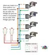
Background: 4 "safety" toggle switches are used to control (Open or Close) a single circuit. The circuit is NOT directly attached to a load but in line with the load circuit. "Safety" (snap cover) switches are in UP (closed) position when armed, the Load circuit needs to be open, and upon changing them (closing cover) to the Down (open) position the Load circuit needs to be closed.

The type of toggle switch ("Safety") is mandatory, therefore its operation is fixed as UP (Closed/On), DOWN (Open/Off) but I need to create a circuit that reverses this result so that when ANY toggle is Open (Down) position the circuit to the load is Closed/On, not Off as is a normal application. How can this be achieved? It cannot be done just reversing wires to pins on switch, or reversing the mounting of the switch because the safety cover is "Keyed" to prevent it. Can a relay be used to reverse the logic of the switch on the switch side of circuit, or Load side of circuit.

Please be aware I can follow direction and drawings but schematics not so much. Any help is appreciated!
 
A diagram would help as I can't understand your description.
It sounds like you just need a relay that's switched by whatever the output is and the NC (normally closed) contacts will do what you want.
Note the relay can be on for a long time so needs to be addequately rated.

Mike.
 
Yes, a relay can use normal or inverted logic, when it is SPDT with normally open (NO) or closed (NC). However, you must ensure the contacts are rated for each application and that you have DC power to drive the coils.

Relays and switches rated>=2A do not use gold-plated contacts.
But < 2A must use gold plating to prevent oxidation.
 
Please note drawing is my logic and does work, except in reverse meaning toggle "safety" feature cannot be used for quick activation because cover can't be slapped UP only down. Could you advise where I would add a relay.
 

Attachments

  • Toggle wireing.jpg
    Toggle wireing.jpg
    45.8 KB · Views: 96
Thanks for responses, confirmation of using a relay helps. As for description, circuits can be Closed (complete flow of current) or Open (current blocked or incomplete), a Phidget is an electronics interface device that controls Input/output signals with a computer. The Phidget is a switch, with pins (connection points) the state of is either HIGH (On, Closed) or LOW (Off, Open) regardless this pin state alone cannot supply enough voltage/amps to operate a light or motor without a RELAY attached that can. You feel you need to Analize the whole project; I asked HOW can I reverse the current flow of a Toggle switch-controlled circuit. Maybe on a 5v 1 amp circuit could have helped, and a schematic too, but I don't know your nomenclature (electrical/electronics) but do know English and drawings. Problem is I can't rise to your level of knowledge for description and you refuse to look at mine.
Thanks again, have a nice day.
 
I think there is some confusion with the end use, as you have shown a switch circuit feeding an electronic input.

With such a use, the effect of the switch circuit can often be reversed by reconfiguring the input connections - not the switch operation itself.


If the switch chain is directly in a power control circuit, you do need a relay.
The whole system then is not failsafe though, as any fault in the switches or power to those puts the relay contact in the "power on" state, so it should not be done like that for anything that has any chance of causing any harm or injury. [There are serious legal liabilities for doing such things].

Positive power (eg. 12V) to one switch wire, the other switch wire to the relay coil positive or A1 terminal (if it has any such markings), the other relay coil terminal to the power supply 0V or negative terminal.
The voltage is not important as long as the power supply matches the relay coil voltage.

The relay coil should have a diode connected across it, if it does not have one built in. eg. a 1N4002 or 1N4007, with the cathode (banded end) to the positive side of the coil.

The relay normally closed contact then works in place of the switches in the original circuit, so the common to NC contact, however it is labelled.
 
It may just be the switch picture you used but how is a toggle switch with a protection cove a safety switch? For them to be activated you need to lift the cover first.

And to reverse the position of the switch to turn something off when slapped down just reverse the cover when mounting the switch.
 
If this is just controlling a logic input to a device can you not just have the signal pulled up by a resistor and the switch contacts just pulls the signal down to ground ?
I think you would need to connect the switches in series rather than parallel to use this method.
More details of the input signal to the "Phidget" would be a great help to solving your problem.
Les
 
I'll rephrase, I have a Slot Car track, the timing software program allows for Power control and external (not just on computer display terminal) of several functions. This is accomplished via an interface (Phidget 1012 board) that is capable of receiving (Incoming) and sending (Outgoing) signals. Specifically, I use a 4-channel relay board to control the Individual power to each of the 4 lanes. Works flawlessly the 5v internal Phidget circuit power, via an outbound pin is connected to the relay board and when triggered allows control of the 20v integrated power supply of the track. In addition, there is a program routine that allows for emergency shutdown of all lanes and suspends timing functions (Pauses race) This is accomplished via an inbound signal from a momentary switch OR other switch. When using a momentary switch, 1st press pauses, 2nd press resumes. If using the toggle, a separate button (switch) needs to be pressed AFTER re-setting the toggle. Now having said all that, it boils down to the Toggle's inherent properties that the switch is designed to be Closed (On) in the up position. When it is in closed (up) position I need the circuit it is attached to be closed, NOT open so that when thrown (Down) the circuit is closed and the signal is sent into the computer. Therefore, the basic question "How can I REVERSE the result of the switch? Note: The cover is keyed so it can't be flipped (mounted upside down), additionally switching the connected wires will not work because they are inline (breaking) one leg of the 5v circuit required of the Phidget both ends are the same wire with switch in middle. It can be done, I had it in place for 5 years before upgrading track. I just can't remember how I did it. I'm not an electrician or electronics tech, but I know what I'm trying to do and that its possible. I can't read or understand schematics, seeing a drawing or someone saying take wire 1 attach it to wire 2... I can do.
 

Attachments

  • Toggle-SafetySw_Vert.png
    Toggle-SafetySw_Vert.png
    87.6 KB · Views: 81
Now we know that this is not a safety critical system I see now reason why you can't reverse the position of the switches.
From the picture in post #10 it looks like the cover part is interlocked with the switch position by either a flat or a grove on the threaded part. The flat or tab on the hole in the cover part could be filed off so the switch could be rotated to any position.
For an electrical solution the switches could feed the coil of a relay and the 5 volt supply to the Phidget could be via the common and NC contacts of the relay. As suggested in post #2
An alternative to a relay woud be a P channel mosfet or a PNP transistor biased on via a resistor. the switches would short the gate to source on a mosfet or base to emitter on the transistor.

Les.
 
Thanks Les, I'm some what better off now than before. Not solution wise but feel better because of being able to show what a Safety Toggle looks like and further discuss what I need to do, by having to express it, I gain understanding as well. Where I know what the terms NC (normally closed) and contacts (connection point) refer to, does not mean I understand what you're trying to say. The switch contacts are labeled Ground/Off, 12v/"+", 20a/Load, and ON, and somehow between their use I could "Feed the coil of a relay" with its output "Supply the Phidget". However, just as the responses to the question has been guarded with "Liability" concerns so is my effort, this is a couple thousand dollars' worth of Racetrack, equipment and I ask because I can't take the chance of connecting it wrong. I conveyed the fact that I don't have expertise in electronics or fully grasp the nomenclature that you feel is common and crystal clear. I don't know what happens in a car engine but know which pedal to push to make it go. I've tried to hire someone but get same canned responses "I don't know Slot cars", "Phidget" what's that", that's why I asked the question vaguely, what I'm using it for is moot, it is not required, it is not your responsibility for answering the question "How do I reverse the result from a switch" but It should be answered in terms I can understand not someone else in the field. I'll add another drawing but keep in mind this is a conceptual drawing made by me of what I think needs to be done. Not even sure if Switches should be in Parallel or Series but in testing it functions BUT IN REVERSE. Where would I connect a relay. As drawn the Orange line is on 12v/"+" terminal, Blue line is on 20a/Load terminal and Green line is on Ground/Off terminal.
 

Attachments

  • Toggle wireing.jpg
    Toggle wireing.jpg
    45.8 KB · Views: 72
If you think of a relay as a switch then using the C (Common) and NC (Normally closed.) contacts there is a connection between them (IE the switch would be on.) when there is no power to the relay coil. These contacts become open circuit (off) when power is applied to the relay coil. So if you connect all of your toggle switches in parallel and in series with the supply to the relay coil then if any (OR more than one.) are in the on position then the relay contacts are in the off condition.
I Googled Phidget and it seemed to suggest that they are a family of devices that interface external inputs to a computer via a USB port. Can you post all of the information on the Phidget that you are using. It may be possible to the signal reversal directly on it's input or in the software that it controls.

Les.
 
When it is in closed (up) position I need the circuit it is attached to be closed, NOT open so that when thrown (Down) the circuit is closed and the signal is sent into the computer. Therefore, the basic question "How can I REVERSE the result of the switch?
Connect the switch circuit between input and ground rather than input and power.

Add a resistor, eg. 1K, between the input and +5V
Done.

The input is high/on UNLESS the switch circuit is made, forcing it off.

(That's what I mentioned, about an easy way to reverse a signal to a logic input bit needing a relay for a power circuit).
 
Yes, Yes, Yes. Thank you, got it! As for Phidiget reversal via software, I cannot do this because the routine for emergency shut down of power is shared with the Ind. Track power and relay. I tried it and then Track Power is Off when it needs to be on. JWR, The phrasing in last post may be saying the same as eariler, but now in a way I understand. Thanks again to all. If any are interested feel free to look into Pepsi Challenge Raceway on Facebook.
 

Latest threads

New Articles From Microcontroller Tips

Back
Top