Chipwizard
New Member
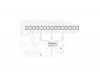
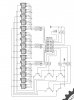
Here is a new project I have been working on. It is an expansion of my previous two versions of color wave. (9 RGB, and 12 RGB) The objective was to create a stand-alone full color (RGB) light array by using one microcontroller(PIC16F628A). The colors on 15 RGB LED's are created and moved across the board per desired color sequence and motion FX. The pcb layout is fairly compact and narrow. (1.25"x7.25") 15 Channels are multiplexed 5x3x3 (5x9).
I am currently working on the firmware given limited time I have and will post once finished.
Cheers
-Rom
I am currently working on the firmware given limited time I have and will post once finished.
Cheers
-Rom