Electro Tech is an online community (with over 170,000 members) who enjoy talking about and building electronic circuits, projects and gadgets. To participate you need to register. Registration is free. Click here to register now.
Welcome to our site! Electro Tech is an online community (with over 170,000 members) who enjoy talking about and building electronic circuits, projects and gadgets. To participate you need to register. Registration is free. Click here to register now.
Is the current through the LED important? i.e. could I use the same circuit but run much less current through the (non-LED) output and everything would still work the same way?
please give me your final circuit diagram Alan. I am also working on replacing my UPS SLA battery with a flooded one and need our circuit. would you help me with your diagram?
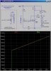
Yes, R3+R4 represents a 1000Ω pot where the pot wiper is being moved during the simulation by the parameter k. R6 (10K) and R8 (42K) biases the pot so its adjustment is not so sensitive. At the point where the LED just comes on, the voltage at the REF pin on the TL431 is 2.495V, so to adapt this circuit so that it works at other trip voltages, you will have to diddle R8 and R6.
R5 controls the current through the LED when it is lit. If you can get by with a dimmer LED, make R5 higher.
The LED can be mounted on the "dashboard", while the rest of the circuit can be in the "engine room". Here is something to mount the LED. **broken link removed** is a Data sheet on the LM431 to show the pin-out. Get the TO-92 version.
can someone help me with a 12v battery monitor to be used in a 12v d.c. to 220v a.c., to monitor the status of the battery using LEDs, also can include an alarm to sound a low voltage level. Thank you
can someone help me with a 12v battery monitor to be used in a 12v d.c. to 220v a.c., to monitor the status of the battery using LEDs, also can include an alarm to sound a low voltage level. Thank you
The TL431/LM431 circuit I posted on Page 1 of this thread will do what you want. It turns on an LED as the battery voltage drops. It is adjustable. You can replace the LED/resistor with an sonalert.
If you want multiple LEDs (a bargraph voltmeter), look at an LM3412.
And here is A Bargraph type battery monitor, my circuit is fitted to my vehicle and works perfectly. It was intended for ham radio oprators who frequently flatten thier car battery while chin wagging on the airwaves.
The circuit also has a 3v buzzer as an audible warning, along with the visual led array. I have included in the picture - box lables and easy steps of part placement on the board.
The pcb size is shown ,and you should print at that exact size for pin hole alignment.
the pcb should not be printed mirrored. the part placement drawing is a view looking through the board like an xray. The tracks being directly underneath.
The case / box used was from maplin uk , and the part number is shown.
I hope the large uploaded picture turns out allright ,as i have tried to put all info
on one drawing.
You never know after an upload how the picture will look, so here goes.
Oh by the way the resistors are not the correct color in the picture regarding thier
values. They are just stamped there to roughly show you where the resistors go.
If i need to modify the circuit for a 6V battery, I just need to play around with R8, the trimpot and R6 right? Could anyone suggest some values please?
Also, I need to protect my battery, so I thought I should connect a relay instead of using an LED. but the problem is the LED turns on when voltage is low... meaning it'd turn on a relay when voltage was low. Quite the opposite, i need to turn it off. i though of scaling down the output to 5V (Voltage divider?), feeding it to an inverter IC (7404), feeding it to a ULN (darlington pair IC to boost current) and then feeding it to a relay (so the relay is off when the voltage is above minimum)... LOL there is probably a simpler way to do this!
The problem with using a relay is that it will suck a continuous 2 to 3W just to keep the coil pulled in. What is the ultimate load that is connected to the battery? Perhaps we can do something involving a FET which will minimize the current drain.
The problem with using a relay is that it will suck a continuous 2 to 3W just to keep the coil pulled in. What is the ultimate load that is connected to the battery? Perhaps we can do something involving a FET which will minimize the current drain.
I'm just using this to power a night light (home made solar lighting project for my backyard ).... its just 30mA for two LED's in series with a 10 Ohm resistor.... and i'll probably have like 10 to 20 of these in parallel... so like 0.3 A to 0.6 A at ~6 V
Yes, then the several hundred mA it would take to pull-in the relay is unacceptable.
Here it is. The current regulation through your LEDs sucks! You need to revisit the forward voltage drop of your LEDs. The voltage of the fully charged SLA will be ~6.6V, and the load should be disconnected when the voltage is ~5.75V.
me too! i'm gonna research some alternatives for on/off solutions to relays.
One is, using an 8051 microcontroller from atmel (AT89C51) so i have control of digital outputs based on an analog input. I can then use an adc to get the voltage of the battery and the amount of light of the surroundings and turn my lights on as required, using a ULN chip (darlington pair) to boost the microcontroller output when i need to turn the led's on.
having a problem with the adc currently.. my programming keeps hanging the chip
Yes, then the several hundred mA it would take to pull-in the relay is unacceptable.
Here it is. The current regulation through your LEDs sucks! You need to revisit the forward voltage drop of your LEDs. The voltage of the fully charged SLA will be ~6.6V, and the load should be disconnected when the voltage is ~5.75V.
oh wow!! thanks so much!! yes... i needed a 30 Ohm resistor to keep the current down to 20mA, but the closest i had was 10 actually i'm using the high intensity white led's rated at 4.5 volts 30 mA max intensity, but i'm giving them 3V each, leaving 6.6 - 6 = 0.6V, dividing by expected current of 20mA, I need a 30 Ohm R in series. If i'm not mistaken your simulation used the green led's rated at 2.2V and 30mA for optimal output. 3 V would burn them and waste energy.
btw what software is that? i use multisim and dont exactly love it. but it gets the job done
This site uses cookies to help personalise content, tailor your experience and to keep you logged in if you register.
By continuing to use this site, you are consenting to our use of cookies.


") ).... its just 30mA for two LED's in series with a 10 Ohm resistor.... and i'll probably have like 10 to 20 of these in parallel... so like 0.3 A to 0.6 A at ~6 V
).... its just 30mA for two LED's in series with a 10 Ohm resistor.... and i'll probably have like 10 to 20 of these in parallel... so like 0.3 A to 0.6 A at ~6 V