Anonymous321
New Member
Hi guys. My first post and thread.
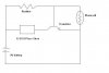
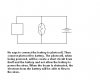
Ok, so I'm making a laser alarm. And I need help. The schematic of what I have is attached. This is what (I believe) happens:
- Photocell is given voltage through laser beam AND 20 1.5 V batteries.
- Voltage flows to the transistor. When there's enough voltage for the base of the transistor (it requires 30V), it opens and voltage flows through the emitter of the transistor. I'm a little sketchy here. So the current from the 9V battery cannot power the siren when the base of the transistor is getting 30V? But how? Like is it that b/c the switch is open, there is not a complete circuit or something for the 9V to power the siren?
- And when the transistor is off (beam is broken), there is a complete circuit (I guess?) and the siren rings.
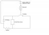
The only part of that circuit that I haven't done yet is the 20 AA batteries connected to the photocell. They should give 1.5V each (so 30V in total) to the transistor so when I have the 9V clipped in, the alarm shouldn't ring, right? (I'm gonna try after this post to see if this happens or not)
But then there's also the problem that if it does work correctly, I don't think that the beam would be doing anything useful b/c it's the 20 AA batteries providing all the 30V. So the only way to turn the transistor off and get the siren ringing is to remove one of the batteries or something. I couldn't tell how much voltage the laser pointer would be giving to the photocell with my multimeter on its lowest-10V-range (the needle just wouldn't move) so I don't know exactly how many batteries I would need. Am I even connecting it properly? I just attach the red and black leads of the multimeter to the 2 leads coming out of the photocell and shine the laser pointer onto the photocell.....The voltage the laser is giving is probably like 0.3V or something anyway. But even then, how would I get something to provide the rest of the 29.7V?? 19 AA batteries would provide 28.5V and the laser's voltage on that will still not be enough for the transistor to turn on.
So I'm really confused on how to go on from here...I would really appreciate it if any of you helped out. Thank you in advance.
Ok, so I'm making a laser alarm. And I need help. The schematic of what I have is attached. This is what (I believe) happens:
- Photocell is given voltage through laser beam AND 20 1.5 V batteries.
- Voltage flows to the transistor. When there's enough voltage for the base of the transistor (it requires 30V), it opens and voltage flows through the emitter of the transistor. I'm a little sketchy here. So the current from the 9V battery cannot power the siren when the base of the transistor is getting 30V? But how? Like is it that b/c the switch is open, there is not a complete circuit or something for the 9V to power the siren?
- And when the transistor is off (beam is broken), there is a complete circuit (I guess?) and the siren rings.
The only part of that circuit that I haven't done yet is the 20 AA batteries connected to the photocell. They should give 1.5V each (so 30V in total) to the transistor so when I have the 9V clipped in, the alarm shouldn't ring, right? (I'm gonna try after this post to see if this happens or not)
But then there's also the problem that if it does work correctly, I don't think that the beam would be doing anything useful b/c it's the 20 AA batteries providing all the 30V. So the only way to turn the transistor off and get the siren ringing is to remove one of the batteries or something. I couldn't tell how much voltage the laser pointer would be giving to the photocell with my multimeter on its lowest-10V-range (the needle just wouldn't move) so I don't know exactly how many batteries I would need. Am I even connecting it properly? I just attach the red and black leads of the multimeter to the 2 leads coming out of the photocell and shine the laser pointer onto the photocell.....The voltage the laser is giving is probably like 0.3V or something anyway. But even then, how would I get something to provide the rest of the 29.7V?? 19 AA batteries would provide 28.5V and the laser's voltage on that will still not be enough for the transistor to turn on.
So I'm really confused on how to go on from here...I would really appreciate it if any of you helped out. Thank you in advance.
")