Electro Tech is an online community (with over 170,000 members) who enjoy talking about and building electronic circuits, projects and gadgets. To participate you need to register. Registration is free. Click here to register now.
Welcome to our site! Electro Tech is an online community (with over 170,000 members) who enjoy talking about and building electronic circuits, projects and gadgets. To participate you need to register. Registration is free. Click here to register now.
She's getting on now, nearly twenty years old.
I tell her its white wine when i put her milk down,
and i tell her its sparkling mineral water when i top up her water.
Those are the PNPs, since the emitter is going in. Yeah, mine are like that (they're shaped like the one with the straight leads). But the Collector-Base is 60V and the Emitter-Base is 6V on mine. Although I think you were just trying to verify the shape. Also, in my circuit, I was trying to use one of the NPN transistors that I have. Both types of transistors that I have are shaped the same way.
The spring box is just a cardboard box. With holes in it. And small springs are inside it. They're just small steels springs and I decided to like crunch my wires in between the springs instead of taping my wires with duct tape.
"I think that siren will only work one way round,
i spose its marked, yes ?" I don't understand? Work one way round? Marked?
**broken link removed**
That is the link for my buzzer. I wrote the specifications earlier too.
And I'm going to go buy a cheap $30 digital camera. Every one I called seems to have theirs "broken". What luck. Just more stress.
But John, would you also happen to have Skype or something so we could talk as well? I dunno, it'd just be better for me to listen to what I have done wrong.
crutschow -- I sort of understand what you are explaining but not really. So how am I supposed to turn the transistor on (ie. don't make the siren ring)? Supply 0.7V to it?
If I understand correctly when the transistor is off, the siren is off. To turn the transistor off you apply less that about 0.6V to the base.
To turn the transitor on requires a current into the base emitter junction (it looks like a forward biased diode). Thus the base emitter voltage will be about 0.7V when applying base current.
No, Sorry,
I have no mike, i do intend to get one and fix up one of the voice systems.
But it will have to wait.
Also i think this sort of thing is best done in the open forums.
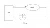
Okay, i looked at the picture of your buzzer/siren.
Yes, one lead is red, that is to indicate positive.
The chances are if you tried it the other way round, that would bust it.
Here is a little picture i have drawn.
Before you put it together with springs, are the springs spaced decently apart?
we dont want any of them touching each other.
The wire you may be using ...
is it insulated wire, which you bare the end a little way for the contact ?
Its not just lengths of bare wire is it ?
Do you reckon you could link up the siren and a transistor like that ?
If you do so it should not operate the siren yet.
I'm back with the camera. A little more expensive than I thought but if this works in the end, it'll be worth it. Have to install some drivers rather...-_-
Insulated wire. Springs are spaced apart. I'll post a picture soon.
The spring box is just a cardboard box. With holes in it. And small springs are inside it. They're just small steels springs and I decided to like crunch my wires in between the springs instead of taping my wires with duct tape.
Sounds like it should do the trick. Same idea as the 30-in-1 or 100-in-1 electronic lab kits sold by Radio Shack back in the day.
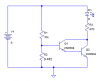
OK, here's a basic circuit. It's essentially the same thing that Hans (AKA Boncuk) posted earlier, except this one uses a Darlington pair instead of just one transistor.
I've drawn this one running from 9V, on the hypothesis that you have a 9V battery and not a 12V battery handy. You can either replace R3 and the LED in my circuit with your buzzer (make sure the + lead goes to V+ and the - lead goes to the collector of the Darlington pair) or just wire it parallel to LED/R3 so that you get light and sound when the beam is broken.
The buzzer should work fine at 9V; just won't be as loud as at 12V. If you want to run the thing at 12V just increase R3 to 680 ohms or so first to protect the LED. (Hm. You don't list 680 ohms in your parts list--so if you run it at 12V, try 1K for R3 and if that's too dim use 330 ohms in series with 470 ohms instead).
When I built this last night it would make a godawful howl unless I kept my cheap laser pointer aimed right at the LDR.
If you have any questions or problems lemme know. This should take about 5-10 minutes to wire together and test using your spring board.
I assume you have an LDR and a laser pointer or similar? Your original post mentioned something about running a laser on 28.5V or so. . .? Cheap laser pointers often just run off of 3 1.5V button cells in series. What kind of laser are you using?
This site uses cookies to help personalise content, tailor your experience and to keep you logged in if you register.
By continuing to use this site, you are consenting to our use of cookies.

")