Continue to Site

Welcome to our site!

Electro Tech is an online community (with over 170,000 members) who enjoy talking about and building electronic circuits, projects and gadgets. To participate you need to register. Registration is free. Click here to register now.

  • Welcome to our site! Electro Tech is an online community (with over 170,000 members) who enjoy talking about and building electronic circuits, projects and gadgets. To participate you need to register. Registration is free. Click here to register now.

zero crossing detector

Status
Not open for further replies.
aibelectronics said:
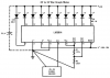
hello guys can anyone figure out how the LM3914 zero-crossing detector in the link below works? i've posted this on another forum and we're all agreed that the 3914 in the circuit had been used strangely...
what's your ideas?

It's only strange in that it's been fed from the AC input, as the article says, it will only respond to the positive side of the signal, and when it becomes positive enough to light that particular LED it will generate a logic signal.

It seems rather a waste of a 3914 though?, surely a simple comparator would do the job much more simply.
 
reply

actually it was powered from a 9v unregulated supply & not AC.
yes it does seem like a waste of the IC, i know a zero crossing detector that uses a 5.1V zener diode and a simple 741 opamp. The 5.1V diode was connected on its feedback loop...
 
reply

i was just wondering, couldn't his intention have been pin 10 and not 17?
i believe led 10 is the first to turn on and the last to go off? hence connecting the input to the buffer could give us a zero crossing detector?
 
Pin 1 is the most sensitive LED output. It goes low when the DC input voltage to the LM3914 exceeds 10% of the reference-out voltage that is set with a trimpot.
Pin 17 goes low when the input voltage exceeds 30% of the ref-out voltage so the LM3914 definitely isn't a zero-crossing detector, no matter which pin is used. :cry:
 

Attachments

  • lm3914_155.png
    lm3914_155.png
    21.1 KB · Views: 1,164
reply

audioguru said:
so the LM3914 definitely isn't a zero-crossing detector, no matter which pin is used. :cry:

darn! that seems to be the final nail on the circuit's coffin. i'll replace it with an opamp zero-crossing detector... but that mistake still give me the doubts over the whole circuit and its associated code.

i wouldn't mind if anyone that comes across any other fault to point it to my short-sighted eyes. :)

somehow, i just can't give up on the project...

a second question pls, the LED's cathodes are connected to the internal comparator's output. when there's a coincidence at it's input the output swings to high, right? wouldn't that be making the cathode to be at the same potential with the anode? how then does the led light up?
 
Re: reply

aibelectronics said:
the LED's cathodes are connected to the internal comparator's output. when there's a coincidence at it's input the output swings to high, right? wouldn't that be making the cathode to be at the same potential with the anode? how then does the led light up?
The LED lights when the output goes low.
audioguru said:
Pin 1 is the most sensitive LED output. It goes low when the DC input voltage to the LM3914 exceeds 10% of the reference-out voltage that is set with a trimpot.
 
i think i'm finally getting how it functions, it's not very accurate though. it seems the author used the 3rd lowest pin so as to allow for the propagation delay of the buffer circuit, through that, there's the hope that the buffer output would actually coincide with the signal's zero crossing...

i now have other challenges:
#1 how do i increase the frequency range, from 1khz? i believe the limitation to 1khz is to severe...

#2 surely one would want to measure other voltage levels as well other than 5v? i'm thinking of using a voltage divider (range selector sort of) at the signal input to increase the range we can measure, but the problem is that, that would always give me a decremated waveform on the screen, smaller than what i'm actually inputting...

any ideas?
 
You want this A to D circuit to operate at frequencies higher than only 1kHz?

1) The old LM324 quad opamp is about as slow as they get. Use a much newer, faster opamp.
2) The 20us sample time for the sample-and-hold stage allows a max frequency of only about 3kHz for terrible 16-steps per cycle resolution.
Use a much shorter sample time.
3) The oscillator in the ADC operates at only 640kHz. Use a much higher frequency for good resolution at higher frequencies.
4) The pc's printer port is very slow with a conversion time of only 100us, which gives a terrible 16-steps per cycle resolution at only 625Hz. Use a USB interface. :lol:
 
audioguru said:
You want this A to D circuit to operate at frequencies higher than only 1kHz?

1) The old LM324 quad opamp is about as slow as they get. Use a much newer, faster opamp.
2) The 20us sample time for the sample-and-hold stage allows a max frequency of only about 3kHz for terrible 16-steps per cycle resolution.
Use a much shorter sample time.
3) The oscillator in the ADC operates at only 640kHz. Use a much higher frequency for good resolution at higher frequencies.
4) The pc's printer port is very slow with a conversion time of only 100us, which gives a terrible 16-steps per cycle resolution at only 625Hz. Use a USB interface. :lol:
I'll add to that:
5) The input resistance is very low and nonlinear (about 900 ohms for negative inputs, 300 ohms for positive).

If you use an op amp as a zero crossing detector, it has to be able to handle the negative input voltages (a series resistor might suffice). The LM3914 is designed to handle negative inputs, but, as has been pointed out, it is a lousy zero-crossing detector.
 
audioguru said:
You want this A to D circuit to operate at frequencies higher than only 1kHz?

1) The old LM324 quad opamp is about as slow as they get. Use a much newer, faster opamp.

Lm 339? Lm 741 perhaps?
 
aibelectronics said:
Lm 339? Lm 741 perhaps?
They are also very old and slow.

The LM339 is a quad comparator, not opamp, and would oscillate with the negative feedback of opamp circuits.

The 741 runs into trouble above only about 9kHz and doesn't work with its input at its negative supply voltage.
 
reply

I'll to add a final one on this post: in the circumstances the LM 3914 was the best option to use, this is because the associated code requires pin 15 to be HIGH throughout the duration that the signal is negative, to enable it plot the negative part of the signal.
On the other hand a 'proper' zero crossing detector only goes high when the signal crosses through zero.
His choice of pin 17 to tap the zero crossing detector might have been as a result of his finding some peculiarity of the circuit...
 
Re: reply

aibelectronics said:
the LM 3914 was the best option to use, this is because the associated code requires pin 15 to be HIGH throughout the duration that the signal is negative, to enable it plot the negative part of the signal.
A comparator IC does the same thing, but its output changes at exactly the zero crossings. None of the comparator outputs of an LM3914 change at a zero crossing.

On the other hand a 'proper' zero crossing detector only goes high when the signal crosses through zero.
Not true. A zero crossing detector's output changes its polarity at each zero crossing.
 
Re: reply

aibelectronics said:
I'll to add a final one on this post: in the circumstances the LM 3914 was the best option to use, this is because the associated code requires pin 15 to be HIGH throughout the duration that the signal is negative, to enable it plot the negative part of the signal.

As I see it the circuit doesn't need a 'zero-crossing' detector?, and the LM3914 doesn't pretend to be any such device. It's using just one of the comparators out of the chip, so it would be simpler to use a single comparator in it's place, which would also allow you to simply adjust the switching point with a preset.

This would simplify the design, reduce it's cost, and give better functionality - the LM3914 is a completely bizarre choice?.
 
reply

thanks guys for the reply, i admit i'm a lot wiser with you two.

the circuit doesn't require a zero-crossing ?
it seemed to me that the need for the zero-crossing arose from this point of the code (in function graphics):

if (e1!=0x08)
{
lineto (c*times, ((may/2) - a1);
}
else
lineto (c*times, ((may/2) + a1));
...

e1 senses the 'logic' of control pin 15. when high it plots the positive part, when low it plots the negative.
 
Re: reply

aibelectronics said:
the circuit doesn't require a zero-crossing ?

The existing circuit certainly doesn't perform that function, it simply triggers high or low at a specific point positive of zero, nothing like a zero crossing detector.
 
Re: reply

Nigel Goodwin said:
aibelectronics said:
the circuit doesn't require a zero-crossing ?

The existing circuit certainly doesn't perform that function, it simply triggers high or low at a specific point positive of zero, nothing like a zero crossing detector.
True, but the circuit does need a comparator to indicate polarity. I believe you and others have already affirmed that.
 
Status
Not open for further replies.

Latest threads

New Articles From Microcontroller Tips

Back
Top