Continue to Site

Welcome to our site!

Electro Tech is an online community (with over 170,000 members) who enjoy talking about and building electronic circuits, projects and gadgets. To participate you need to register. Registration is free. Click here to register now.

  • Welcome to our site! Electro Tech is an online community (with over 170,000 members) who enjoy talking about and building electronic circuits, projects and gadgets. To participate you need to register. Registration is free. Click here to register now.

XR2206 function generator IC unstable when using above 10V supply

Status
Not open for further replies.

riccardo

Member
Hi,

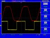
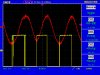
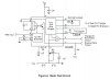
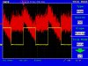
I've built the basic test circuit shown in the datasheet for the XR2206, it works ok, but when I'm turning up the supply beyond 10V, the output becomes unstable and the frequency wobbles around.

https://www.electro-tech-online.com/custompdfs/2011/07/XR2206V1PDF.pdf (See figure 2)

The datasheet says I can use from 10V to 26V for the supply, yet the distortion in the output seems to increase significantly with voltage above 10V.

I've tried adding decouplers/bypass capacitors in various places but nothing seems to make a difference. Anyone got any suggestions??
 
hi,
A possible cause maybe your PSU, is it stable and ripple free at the higher voltage outputs.???
 
Yes, it's a half decent bench supply, I've tried adding capacitance on the supply outputs too but makes no difference. I am trying to test it on a breadboard though. I've never seen a similar effect before with any other circuit on my breadboard.
 
Maybe it is your board layout, Noisy supply maybe? Power leads to thin and long. Poor grounding. Could be a number of things. Are you using a breadboard? If so the breadboard may be causing weird oscillations.
 
OK,
Have you read about R3 in the d/s about its 'best' value for the required Vsignal output.?
 
Is it the amplitude or frequency or both thats unstable.?

EDIT:
Is there any 'instability frequency' superimposed on the basic frequency.. ie mains hum etc.??
 
Last edited:
The capacitance between tracks on a breadboard and the long connecting wires (antennas for mains hum) cause many circuits to not work properly. I didn't mention the many intermittent contacts.

Why not quickly design a compact stripboard or pcb layout and SOLDER the connections?
 
It is the frequency that's jumping around. I've attached scope shots at 10V and 25V.
At 25V the sine has lots of noise. The frequency of both is jumping around on both, although that is hard to see from the scope still.
 

Attachments

  • 2206---10V.jpg
    2206---10V.jpg
    118.4 KB · Views: 573
  • 2206---25V.jpg
    2206---25V.jpg
    122.9 KB · Views: 368
hi,
Even at 10V the sine wave is being clipped.?
I can see the change in the square wave mark/space at 25V.

It could be the bread board, I have used breadboard OK with the XR2206 and it worked fine.?

The proof could be to build the circuit on a PCB, using strip pcb.
 
Yes, clipped at 10V, but when higher volts it seems not to be clipped, but then the noise appears.

I've just made a PCB and the problem still persists! :(
 
See attached.
 

Attachments

  • xr-2206-top.JPG
    xr-2206-top.JPG
    157.5 KB · Views: 1,747
  • xr-2206-bot.JPG
    xr-2206-bot.JPG
    218.5 KB · Views: 542
  • xr-2206-sch.JPG
    xr-2206-sch.JPG
    34.2 KB · Views: 1,390
I'm using a split supply, therefore all the GND points in the diagram go to negative rail, and I use the supply GND instead of the resistor divider near pin 3. (I tried the resistor version on single supply too but same result)
 
What is the ripple on you power supply? Using AC on your scope input. I know it is a "good bench supply" but......
 
I wouldn't say "good", just half decent!:p

Might be onto something here. With scope between + and - on the supply, the reading is between 12mV and 20mV (15mV typical) RMS which seems quite a lot to me.

When I measure between GND and a rail there's a 250mV 50Hz signal. This drops to 50mV when my circuit is attached, but that still seems like loads!
 
Your power supply has tonnnnnes of hum and needs more filtering and maybe a voltage regulator IC.
 
I wouldn't say "good", just half decent!:p

Might be onto something here. With scope between + and - on the supply, the reading is between 12mV and 20mV (15mV typical) RMS which seems quite a lot to me.

When I measure between GND and a rail there's a 250mV 50Hz signal. This drops to 50mV when my circuit is attached, but that still seems like loads!

hi.
I suggested this could be the problem in my post #2.
 
The amount of ripple is still the same at 10V input yet everything works fine. It's only turning up the voltage that seems to set it off. Anyway, will try with a pair of 12V batteries and see how that goes!
 
Ok, so same result even on a battery. It's not the PSU.

I have noticed that if I use a larger timing resistor such as 1M, the problem becomes significantly worse. Unfortunately, using a much smaller resistor does not make it better.

Tried all sorts of combinations or R & C, but can't get it to be better. I've attached a shot of the signal I measure on the timing cap (scope on AC coupling). Seems messy, is that how it should look?
 

Attachments

  • 2206---Cap.jpg
    2206---Cap.jpg
    124.8 KB · Views: 325
Status
Not open for further replies.

Latest threads

New Articles From Microcontroller Tips

Back
Top