Continue to Site

Welcome to our site!

Electro Tech is an online community (with over 170,000 members) who enjoy talking about and building electronic circuits, projects and gadgets. To participate you need to register. Registration is free. Click here to register now.

  • Welcome to our site! Electro Tech is an online community (with over 170,000 members) who enjoy talking about and building electronic circuits, projects and gadgets. To participate you need to register. Registration is free. Click here to register now.

XOR and KYB power supply

Status
Not open for further replies.
KMoffett: no problem man, I just hope you'll get better soon.

I connected the "stuff" and it works!!!! I think I'm getting hooked.

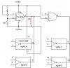
I bought a quad switch from TI today (4 pieces - just in case), and I want to control 4 different signals (two at a time) with the XOR gate, and the pushbutton.

Below is a schematic, and again I'm asking for some tutelage. I don't know why but it seems right to me to connect an extra 10K resistor (RED resistor) between the exit of the first XOR gate and the input of the second XOR gate? Is there any difference at all?

What if I decided to use just 2 signals, how do I connect the rest of the input output pins on the switch chip?

And just in case you are wondering - I still use macromedia fireworks for the drawing - haven't got used to ExpressPCB jet :D
 

Attachments

  • vezje5.jpg
    vezje5.jpg
    27.4 KB · Views: 144
Well - being honest - I don't know yet, I'm just experimenting with different electronic components. I guess I'll try to power different LEDs from different supply voltages.

Why, is there something terribly wrong with the circuit???
 
volk said:
Well - being honest - I don't know yet, I'm just experimenting with different electronic components. I guess I'll try to power different LEDs from different supply voltages.

Why, is there something terribly wrong with the circuit???
Just be aware that CD4016 is far from an ideal switch. It has a lot of resistance, and that resistance varies, depending on the voltage on the signal pins. It also depends on your supply voltage. By all means experiment, but keep this in mind.
 
Thanks - could you recommend a better switch which can be controlled with 5V voltage, that is also the supply voltage. The signal pin voltage probably wont exceed 7V?

But the schematics is OK? What about the extra resistor (the red one)?
 
volk said:
Thanks - could you recommend a better switch which can be controlled with 5V voltage, that is also the supply voltage. The signal pin voltage probably wont exceed 7V?

But the schematics is OK? What about the extra resistor (the red one)?
I would get some 74HC4066's, or 74HCT4066's. Their ON resistance is on the order of 40 ohms. Do not exceed 5V on the signal pins. Do not exceed 20mA per switch.
The extra resistor does nothing. CMOS logic gates have internal pullup and pulldown output transistors, so external resistors on the output generally just waste power.
 
If you want to experiment some more,you can replace the XOR that you are using as an inverter with one section of a 74HC4066 and a resistor. See the schematic below.
 

Attachments

  • 4066 inverter and switches.PNG
    4066 inverter and switches.PNG
    21.7 KB · Views: 169
Status
Not open for further replies.

Latest threads

Back
Top