Electro Tech is an online community (with over 170,000 members) who enjoy talking about and building electronic circuits, projects and gadgets. To participate you need to register. Registration is free. Click here to register now.
Welcome to our site! Electro Tech is an online community (with over 170,000 members) who enjoy talking about and building electronic circuits, projects and gadgets. To participate you need to register. Registration is free. Click here to register now.
Can anyone explain to me the xnor circuit that attached why there is not always the led be on;
because the current from 9V will flow through R1 to the collector of T2 and to the emitor of T2
and of course the current will flow to R2 to the base of T2 to the emitor of T2 and the current will light up led L1.
So the led should always be on.
If either of the two inputs are high, then T1 will be turned on and it's collector will be at gnd. Of course, this means that there will be zero volts at R2 and the collector of T2, so no current will flow to the LED.
PS. Please add values to all components in your schematics. And mark the two inputs so they match those in your truth table.
But you could also ask yourself why when both inputrs are low
all the voltage will not fall on R1,
but part of the 9V will fall on R1 and the other part will fall on R2?
Look to the two inputs... If both are on T3 and T4 light the LED.. If both are off T2 lights the LED as T1 is off .. If only one is on, T3 or T4 alone do not complete the circuit and T1 stops T2 from completing the circuit.
If only one is on, all the 9V falls on R1 so no current flows through R2 and that is the reason that T2 is off.
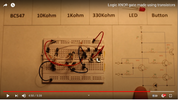
But I am talking about the breadboard in the picture.
How he connected all the components to form the xnor circuit.
This site uses cookies to help personalise content, tailor your experience and to keep you logged in if you register.
By continuing to use this site, you are consenting to our use of cookies.