Continue to Site

Welcome to our site!

Electro Tech is an online community (with over 170,000 members) who enjoy talking about and building electronic circuits, projects and gadgets. To participate you need to register. Registration is free. Click here to register now.

  • Welcome to our site! Electro Tech is an online community (with over 170,000 members) who enjoy talking about and building electronic circuits, projects and gadgets. To participate you need to register. Registration is free. Click here to register now.

xc705k1cp pinout request

Status
Not open for further replies.

Ken1

Member
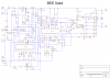
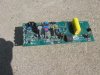
Does anyone know the pinout of a Motorola XC705K1CP 16 pin dip ic? Google can't find a datasheet online. I am trying to figure out why a battery/solar panel farm fencer will not charge the high voltage storage capacitor and this ic is part of the electronics that operate the mosfet switch transistor.
 
On my chip pin 13 is +5v, pin 14 is ground and pins 15 and 16 have a 4 MHz ceramic resonator attached.
 
On my chip pin 13 is +5v, pin 14 is ground and pins 15 and 16 have a 4 MHz ceramic resonator attached.

Which points even more towards it been a micro-controller - as does the four pins you mention been the right pins for a MC68HC705K1 as already suggested.

So, as already suggested, the datasheet (which is freely available) won't be of much help to you, as it's function depends entirely on it's programming.
 
The pin numbers you list are different that those of the chip I mentioned in post #2, but the presence of and oscillator (the ceramic resonator) almost guarantees that it is a microcontroller.

That it's a Motorola part with a similar number indicates to me that it's probably a different member of the same family.

I'm afraid that your best bet for trouble shooting and repair is information from the company that made it. Or post the make and model of the fencer itself (with pictures) here and see if anyone is familiar with it and it's problems.
 
The pin numbers you list are different that those of the chip I mentioned in post #2.


??? - looks spot on to me.

68HC705K1.png
 
The fencer is a Bee Solar Farm Fencer model 9444. Attached are a photo of the board and a schematic I drew up. Capacitors C19 - C22 on the schematic do not charge at all. They are supposed to charge up to several hundred volts. The trip pulse to the gate of the scr is present. and the pulse frequency switch works and does adjust the tripping frequency between 1, 2, and 4 seconds apart.
 

Attachments

  • Bee 9444a.png
    Bee 9444a.png
    34.7 KB · Views: 113
  • IMG_0063b.jpg
    IMG_0063b.jpg
    1.4 MB · Views: 120
Status
Not open for further replies.

Latest threads

New Articles From Microcontroller Tips

Back
Top