Electro Tech is an online community (with over 170,000 members) who enjoy talking about and building electronic circuits, projects and gadgets. To participate you need to register. Registration is free. Click here to register now.
Welcome to our site! Electro Tech is an online community (with over 170,000 members) who enjoy talking about and building electronic circuits, projects and gadgets. To participate you need to register. Registration is free. Click here to register now.
Hi all
I've found a project that should do what I've written in the subject of the thread.
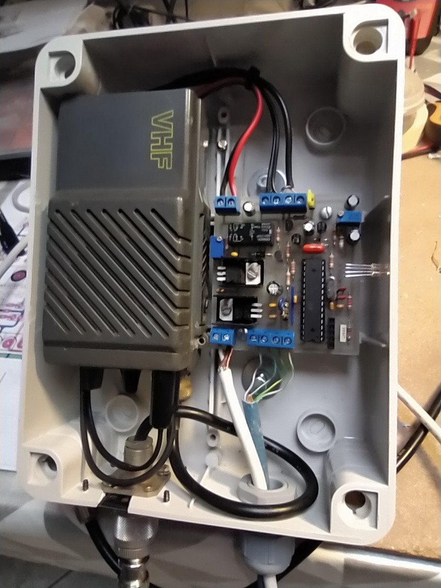
Arduino is connected to a VHF Intek transceiver.
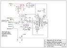
What do you think the circuit in the red circle do?
Thanks
It's to prevent the transmitter being stuck on continuous transmit if something goes wrong with the MCU circuit / software.
When it's idle, the right hand of the 100uF cap will be at about 5V and the left hand at about 0.7V, the transistor base-emitter voltage.
When the MCU switches to transmit, both sides of the cap will initially be pulled down by around 5V, so the right hand side is near 0V and the left at around -4.3V
The cap will immediately start discharging the 150K and the left hand side voltage will progressively increase, until the left BC547 switches on again and shuts off the BC337 PTT driver.
When the MCU switches the TX control back to 0V, the capacitor recharges charges via the 5K6 resistor and everything resets.
The capacitor is backwards... It's normally positive at the right-hand side and only the opposite polarity if the transmit time exceeds the permitted duration.
I'd reverse that and add a series diode in the collector of the right hand transistor so the other components cannot be pulled down below 0.6 - 0.7V, to avoid any possible reverse voltage on the cap.
Se trovate tra i calcinacci di un cantiere una scatola stagna Gewiss, se avete un vecchio portatile a contraves senza subtoni disoccupato, se in cantina da anni vi gira tra le bottiglie una antenna…
iw1cgw.wordpress.com
I think I will use an Arduino nano board as a component to semplify the pcb design.
p.s. do you have any idea why 2 different kind of npn bjt were used? Couldn't I just use P2N2222A?
I'd reverse that and add a series diode in the collector of the right hand transistor so the other components cannot be pulled down below 0.6 - 0.7V, to avoid any possible reverse voltage on the cap.
I'd just reverse the capacitor (as you say it's the wrong way round), but nothing else is needed - particularly as the supply is only 5V - main issue would be reverse Vbe breakdown, but the transistor is rated at 6V.
Se trovate tra i calcinacci di un cantiere una scatola stagna Gewiss, se avete un vecchio portatile a contraves senza subtoni disoccupato, se in cantina da anni vi gira tra le bottiglie una antenna…
iw1cgw.wordpress.com
I think I will use an Arduino nano board as a component to semplify the pcb design.
p.s. do you have any idea why 2 different kind of npn bjt were used? Couldn't I just use P2N2222A?
BC337 is higher power, so can switch a larger load than the BC547, the P2N2222A should be fine for both (as it's similar to the BC337) - although I suspect the BC547 would be fine for both as well.
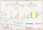
OK, I've tried to redesign this board using an Arduino Nano board.
This project has a remote i2c sensor (BME280). I have place pullup resistors in its cable connection. Is it ok?
Are the polarities of the capacitors in the radio_mic section ok?
Do you see any major flaws?
Thanks
I would definitely add a diode in series with Q4 collector. It should never matter - the same as the entire TX time limit circuit....
But if you are including that, it seems daft leaving the slightest possibility that it will not work as intended.
You could just relocate D4, as I cannot see how that one ever does anything possibly useful.
(Possibly an earlier version did not include Q4, so it was to protect the MCU pin, in which case it was required - but not now, with the transistor there).
IF...... the CPU operation ever messes up and the MCU transmit output stays locked high, R10 will discharge the cap[ so the left side is around 0.6 - 0.7V, so Q2 turns on and the left side of the cap is then fixed at that voltage until the transmit command switches off.
Without the diode, the right side of the cap would be at probably 0.1V or less, whatever saturates at.
That would mean the cap is slightly reverse polarised.
It's unlikely to do any short term damage, but eventually the cap could degrade and depolarise, messing up the timer - or at worst case going so leaky that the left side was also pulled slightly down and the transmitter switched back on!
To me it's a waste to go to the trouble of a failsafe circuit, then leave a silly problem that could cause the failsafe to fail!
With the diode added, the cap should never be reversed polarised as the right side cannot go below 0.6 - 0.7V, the diode drop plus the transistor saturation voltage.
I have asked the guy who has designed the original circuit.
He told me that particular watchdog circuit is used since 90s in this kind of projects involving TNC packet radio...
Any thoughts?
I have asked the guy who has designed the original circuit.
He told me that particular watchdog circuit is used since 90s in this kind of projects involving TNC packet radio...
Any thoughts?
As I said in post #6, the original capacitor was the wrong way round - this WILL cause problems, and the capacitor will fail prematurely - as Samsung found out when they accidentally fitted a capacitor the wrong way round in a range of their VCR's (some didn't make a year, some made a bit longer than a year).
Simply turning the capacitor round the correct way is the only action needed, the tiny 0.6V reverse polarisation is perfectly acceptable, perfectly normal, and causes no issues.
This site uses cookies to help personalise content, tailor your experience and to keep you logged in if you register.
By continuing to use this site, you are consenting to our use of cookies.