Hello forum ! I want to create a circuit, that will produce a 12v output signal, when my car alarm in NOT armed..
So, what i have :
An aftermarket alarm system, that only has a GND output, when the system IS armed..
Also, it produces 12v square pulse, when the systems is arming/de-arming for the doors to lock/unlock
What i want :
To have a 12v signal (that will be used to drive some relays maybe) ,when the car alarm is not armed.
And the whole circuit should not be consuming any current at all, when the car alarm is armed...
i have come up with the following circuit :
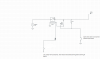
will it do what i want?? what tipe of transistor should i use?? (MOS or BJB , and N or P ) ?? thanks !
any feedback is appriciated !
So, what i have :
An aftermarket alarm system, that only has a GND output, when the system IS armed..
Also, it produces 12v square pulse, when the systems is arming/de-arming for the doors to lock/unlock
What i want :
To have a 12v signal (that will be used to drive some relays maybe) ,when the car alarm is not armed.
And the whole circuit should not be consuming any current at all, when the car alarm is armed...
i have come up with the following circuit :
will it do what i want?? what tipe of transistor should i use?? (MOS or BJB , and N or P ) ?? thanks !
any feedback is appriciated !
Attachments

Last edited:

