Continue to Site

Welcome to our site!

Electro Tech is an online community (with over 170,000 members) who enjoy talking about and building electronic circuits, projects and gadgets. To participate you need to register. Registration is free. Click here to register now.

  • Welcome to our site! Electro Tech is an online community (with over 170,000 members) who enjoy talking about and building electronic circuits, projects and gadgets. To participate you need to register. Registration is free. Click here to register now.

Would like some help, please, to ID these components

Status
Not open for further replies.

Simon822

Member
Would like some help, please, to ID these components.

"A picture says 102 words", please see attachment:)

Thank you, ahead
 

Attachments

  • 11 - Current_regulator_circuit - 22-5V B&W.jpg
    11 - Current_regulator_circuit - 22-5V B&W.jpg
    65.2 KB · Views: 309
Welcome to ETO, Simon822!

Essentially, this circuit:
upload_2016-6-29_18-3-48.png


Is this a homework assignment?
 
Welcome to ETO, Simon822!

1). Thank you

2). I wish it was...

3). Reason for the picture, instead of a blueprint, is that I cannot read blueprints. Sorry...

4). So, I'm back to square 1. Anyone else, can help me ID the transistor and resistor?
 
Last edited:
Hy Simon822,

I see you are from the USA: which state?

cowboybob has your circuit above- just remove the laser and that is it.

It is a widely used constant current generator that relies on the fact the the emitter base voltage of a silicon transistor is more or less constant at 0.6V. Thus Q1 uses negative feedback to control the base emitter voltage of Q2 and keep the voltage across R2 at a constant 0.6V.

As the constant current output of your circuit is 5mA that means that R2 = 0.6V/5mA= 120 Ohms.

R1 provides some current for Q1 to conduct and also the base current to allow Q2 to conduct 5mA.
Assume that the hFE (current gain) of Q2 is at least 100 then the base current of Q2 will be 5mA/100= 50 micro amps.
Then chose a suitable collector current for Q1 which should be at least 10 times Q2 base current =500 micro amps, say 2ma. Then R1 = (22.5V- 0.6V)/2ma= 10.95K Ohms, so the 10K Ohms value for R1 in cowboybob's circuit is ideal.

In terms of transistors, Q1 and Q2 are both small signal silicon NPN bipolar junction transistors that, unlike in a current mirror, do not need to be matched or in thermal contact with each other. In fact, it would be better if they were not in contact with each other. The two transistors do not even need to be the same type number. As a result, there are literally hundreds of transistor types that will suit this circuit. Note though that different families of transistor have different pin outs (the collector, base, and emitter are connected to different leads coming out of the transistor case). You can check the pin out by referring to the transistor data sheet.

For example, the BC547 that cowboybob shows is an excellent choice.

Some other suitable transistors are:
BC546, (BC547), BC548, BC549, BC550. Data sheet: http://www.fairchildsemi.com/datasheets/BC/BC547.pdf
BC107, BC108, BC109. http://www.centralsemi.com/get_document.php?cmp=1&mergetype=pd&mergepath=pd&pdf_id=bc107.PDF
BC182, BC183, BC184. **broken link removed**
2N3707, 2N3708, 2N3709, 2N3710, 2N3711. http://www.mouser.com/ds/2/68/2n3707-3711-15606.pdf
2N3903, 2N3904. http://www.onsemi.com/pub_link/Collateral/2N3903-D.PDF

spec
 
Last edited:
Hi Spec thank you kindly for your time & help,,,
(observing the picture-attached again), could be that the

- #2, is a: 2N2222A transistor,,,

- I'm suspecting same with the #4!?

- Any one else would like to pitch in, please?
 
Hi Simon822,
Some background information would help. For example Is is a homework / exam question ? Is it something you are trying to repair ? Is it something you are trying to build from a design on the web ? What is the power source and what is the load it is feeding ?

Les.
 
Hi Les, thank you.
- As title says.
- CC Power Supply.
- I have included a picture, at the top post, please.
 
Last edited:
Hi Spec thank you kindly for your time & help,,,
(observing the picture-attached again), could be that the

- #2, is a: 2N2222A transistor,,,

- I'm suspecting same with the #4!?

- Any one else would like to pitch in, please?

No problem Simon822,

Yes, a 2N2222A transistor would work OK too in positions #2 and #4: https://www.onsemi.com/pub_link/Collateral/2N2222A-D.PDF

By the way, you can make a compliment to the constant current supply by using PNP transistors. That way the load would be OV referenced. If you would like a schematic just ask. :)

spec
 
Yes a 2N2222A transistor would work OK too in positions #2 and #4: https://www.onsemi.com/pub_link/Collateral/2N2222A-D.PDF

Electronics are part of our daily life, for some of us, and I'm starting

to realize how much fun would be to understand and apply it.

Back to the picture at the top:

- #3 seems to be 210 ohms! (1/4 or 1/2 Wat!)

- #1 seems to be 2,500 ohms! (1/4 or 1/2 Wat!)


Two questions, please:

- Would there be any free software, to draw correctly this diagram,
assuming it was ID'd correctly, and it works in real practice.

-Would there be some sort of formula to check these values:
volts, resistance, ohms, etc?

Thank you Spec
 
Last edited:
Electronics are part of our daily life, for some of us, and I'm starting to realize how much fun would be to understand and apply it.

Back to the picture at the top:

- #3 seems to be 210 ohms! (1/4 or 1/2 Wat!)

- #1 seems to be 2,500 ohms! (1/4 or 1/2 Wat!)

Two questions, please:

- Would there be any free software, to draw correctly this diagram,
assuming it was ID'd correctly, and it works in real practice.

-Would there be some sort of formula to check these values:
volts, resistance, ohms, etc?

Thank Spec

Yes, electronics is very interesting and it is not that hard to learn the basics. As you are in Ohio you will be able to get all the information, components and tools you would need.

The answer to your two questions are yes.

You can download a free copy of Cadsoft EAGLE to draw schematics:

With EAGLE you can draw electronic schematics and even layout printed circuit boards. EAGLE is very easy to use. Many of us on ETO use it.

My post #4 above gives an explanation of the circuit function and also the formulas to use.

With #3 equal to 210 Ohms the constant current would be 0.6V/210 Ohms= 2.9 mA not 5 mA. To get a constant current of 5 mA resistor #3 needs to be 120 Ohms.

With resistor #1 at 2,500 Ohms, the current through the first transistor (#2) would be (22.5- 0.6V)/2,500 Ohms= 8.76 mA which will be OK.

Spec

PS: I just realized that the transistors that I listed in post #4 were not physically the types shown in your picture which are in a metal can. The other type of case is plastic which is more common and cheaper. Electrically the transistors are the same though (in this circuit).
 
Last edited:
Hi Simon822,
If you can take a colour picture of the circuit we could read the value of the resistors. I dont think the resistor item 3 can be 210 ohms. (You don't say if you measured it or you tried to read the colour code.) Here is the reasoning for thinking resistor item 3 will be about 120 ohms. Looking at the schematic provided by cowboybob in post #2 (Which I agree with although the transistor types are different.) For an silicon NPN transistor when the base - emitter voltage reaches about 0.6 volts the transistor starts to conduct. (Current flows between collector and emitter.) When the voltage across resistor item 3 (R2 in the schematic) reaches 0.6 volts it causes transistor item 2 ( Q1 in the schmatic.) to start to conduct. This reduces the base current into transistor item 4 (Q2 in the schematic.) which in turn reduces its collector current which is the 5 mA output current of the circuit. As the current through resistor item 3 (R2 in the schematic) is mainly the 5 mA output current then its value must be 0.6 volts divided by 0.005 amps (5 mA) so 0.6/0.005 = 120 ohms. This is the only value we can work out. The value of the other resistor item 1 (R1 in the schematic) does not need to be an exact value. One of the previous posts has shown how to estimate a suitable value.
There is a free software package for drawing schematics (And PCB layouts.) it cab be downloaded from
Les.
 
Last edited:
If you can take a colour picture of the circuit we could read the value of the resistors.

Thank you, Les.

- Bottom Transistor, I cannot make which poles are attached: "A" or "C" is the closest to Red + wire!?

- Top Transistor, I cannot even begin to guess.

- An "expert" like my self, probably could check - resistance of a Transistor?

(I was reading on line, and in case of my exhibited example in the attachment, the metal
casing has a slight "tongue", and I'm trying to figure this out!?)

(Please, see Transistor poles in the picture attached).
 

Attachments

  • 11 - Current_regulator_circuit - 22-5V.jpg
    11 - Current_regulator_circuit - 22-5V.jpg
    59.2 KB · Views: 218
Last edited:
Hi Simon822,
You colour picture confirms that the resistor item 3 is a 120 ohm 5% tolerance resistor. Starting from the right hand end of the resistor the colours are brown, red, brown gold. The first brown represents the digit 1, the red represents the digit 2 the next brown is the decimal multiplier. (This is the number of zeros that follow the first two digits. So we have 12 followed by one zero which is 120. (If the colours had been brown, red, red then it would have been 12 followd by two zeros = 1200 ohms) The gold band shows its is 5% tolerance. The resistor item 1 is 15K ohms (15000 ohms) 5% tolerance resistor. The colours starting from the right are brown, green, orange. Brown is 1, green is 5 and orange is 3 (Representing 3 zero's) So we have 15 followed by 3 zero's = 15000 (Or 15K) The gold band again indicates 5% toleance. As you managed to take a colour photograph it seems possible that you may physicaly have the circuit. If so can you take a macro picture of the numbering on both transistors. (This is one reason for asking for background infromation that you will not provide.) The tranistor package type of the transistors is TO-18. The normal pin layout for this type of package is the tab (A in your picture) is the emitter. B in your picture is the base and C is the collector. (There are exceptions to this layout.) From the shaddow on the picture of transistor item 2 you can see that the tab is on the left which is the emitter which is connected to the negative rail. (Black wire.) The base (terminal B in your picture.) connects to one end of the 120 ohm resistor and the emitter of transistor item 4. The collector (Terminal C in your picture) connects to one end of the 15K resistor and the base of transistor item 4. The collector of transistor item 4 connects to the negative output of the circuit.
The junctions in a transistor do not behave like a normal resistor. (The don't obey ohms law.) They behave more like two diodes with the anodes connected to the base terminal (For an NPN transistor)

Les.
 
We haven't answered your question about resistor power rating in Watts yet.

The power rating is how much power, in Watts, that a resistor is able to take without damaging or destroying itself.

So first you work out the power dissipation that the resistor has in a particular place in a particular circuit.

Then you chose a resistor that has a higher power rating than the actual power the resistor will be taking in the circuit.

The power rating of a resistor has absolutely no effect on the electrical performance of a resistor (this is not quite true, but for this circuit it is).

Resistors come in standard power ratings, and the higher the power rating, the bigger the resistor normally is.

The normal resistor power ratings are: 0.125 Watts (eighth Watt), 0.250 Watts (quarter Watt), 0.5 Watts (half Watt) and 1 Watt (one Watt).

There are then the high power resistors of: 2 Watts, 3 Watts, 5 Watts, 10 Watts, 15 Watts .... 100Watts.

After that there are the very high power resistors up to any wattage you can think of. Incidentally, electrically, your kettle at home is nothing more than a 1000 Watt to 3000 Watt resistor.:)

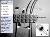
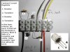
As Les has deduced from your photograph one resistor in your constant current circuit is 15 000 Ohms and the other resistor is 120 Ohms

The 15000 Ohm resistor has 22.5V- 0.6V = 21.9V across it. The power in a resistor is V*V/R Watts so this resistor will be dissipating 21.9V * 21.9V/15000 Ohms in Watts. Thus the power dissipation in the 15000 Ohm resistor will be 0.032 Watts so any resistor will be OK from a power rating aspect.

The 120 Ohm resistor has 0.6V across it, so the power dissipated will be 0.6V*0.6V/120 Ohms in Watts. So the power dissipated by the 120 Ohm resistor will be 0.0003 Watts. Once again any resistor will be suitable, from a power rating aspect.

spec
 
Last edited:
Spec, and fellows above,,, this one was above and beyond, "the call of duty"! I'm grateful, very much appreciative, amazed, very thankful on how much others go out of their way to help someone needing help in this field... yet 60 yrs ego if I would have known how advanced electronics would become, in time, I would have given a part of my life to it without hesitation or reservation.

Many thanks, and blessing to all of you. I will try to put together this "prescription" , and report back on my success.

Best regards

Simon
 
You're welcome, Simon.

Never too late to dive in. Lots of experience, talent and a remarkable willingness to help here, especially spec and les.
 
You're welcome, Simon.

Never too late to dive in. Lots of experience, talent and a remarkable willingness to help here, especially spec and les.
and cowboybob :)

Yes, it is never too late to start in electronics, besides which you are quite young compared to some of us.

Good luck with your electronic endeavors.

spec
 
Last edited:
I'm pleased that we seemed to have solved your problem even though we still have not been given the full details. Have you repaired it ? Have you made it and does it work ? It very often helps a lot to know the background information on a problem for many reasons. In certain cases even the OPs location is helpful in suggesting sources of components and the problem may be dependent on the mains voltage and frequency. There are a small number of cases where the OP has good reason to withhold information if the problem relates to the design of a comercial product. I still don't understand why you refused to give any background information.

Les.
 
Hi Les,

Nothing escapes trained eye of esteemed and expert, fellow member.
Perhaps these few lines will shed some light.

- Picture was the only thing I had to work with, from very beginning.

- Close examination, and humble layman eye, have discovered transistor type.

- Was corrected by fellow member regarding resistor type. (Have spent some time on
line and also purchased a set of various resistors, in an effort to identifying same, from a list enclosed.)

- Need to locate a pair of transistors, prior commencing to apply knowledge acquired from this forum.

- Yes I could use some schematics on this simple project, (perhaps with new discovered specs, if possible).

- Have forgot to ask fellow members as to the range of voltage.

- Instance given of the top of my head was 22.5 Volts! Would there be a range from lets say 12 Volts - 24 Volts?
With same specs above?

Thank you so much

Simon
 
Hi Simon,
12 volts is probably a little on the low side if the load has a voltage of 10 volts across it with 5 mA passing through it. (I am thinking the secret application may be 3 small white LEDs in series.) There needs to be a couple of volts across the pass transistor (Item 4) for it to work properly. I think with any of the transistors suggested you should be OK with a supply voltage up to at least 30 volts. We could probably find transistors to allow you to go up to a few hundred volts input if you require this. One of the difficulties with the original question was the phrase identify the components. It could have been interpreted as the actual transistor used in the circuit in the picture rather than just a type of transistor that would serve the purpose. The 120 ohm resistor was the only component that could be specified precisely.

Les.
 
Status
Not open for further replies.

Latest threads

New Articles From Microcontroller Tips

Back
Top