Continue to Site

Welcome to our site!

Electro Tech is an online community (with over 170,000 members) who enjoy talking about and building electronic circuits, projects and gadgets. To participate you need to register. Registration is free. Click here to register now.

  • Welcome to our site! Electro Tech is an online community (with over 170,000 members) who enjoy talking about and building electronic circuits, projects and gadgets. To participate you need to register. Registration is free. Click here to register now.

Would like some help, please, to ID these components

Status
Not open for further replies.
Hy Simon822,

- Need to locate a pair of transistors, prior commencing to apply knowledge acquired from this forum.
- Yes I could use some schematics on this simple project, (perhaps with new discovered specs, if possible).
- Have forgot to ask fellow members as to the range of voltage.
- Instance given of the top of my head was 22.5 Volts! Would there be a range from lets say 12 Volts - 24 Volts? With same specs above?

Here are the answers to your questions in post #19 and some basic electronic theory along with schematics of a high side (positive supply) referenced constant current generator and an inverted form, a low side (0V supply line) referenced constant current generator. Both of these circuits are widely used in electronics. R1 value has been changed to maximize the supply line voltage range.

(1) Answer to Questions
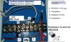
(1.1) Any of the transistors that I listed in previous posts will be suitable and will give equal performance, although most are plastic cases rather than metal can as shown in your picture of the constant current circuit. I would advise you to use a pair of BC546 NPN plastic case transistors.
(1.2) Schematics are posted below.
(1.3) The voltage range of the circuit posted below will be from 2V to the maximum allowable voltage, collector emitter (VCE), of the particular transistor used.
The maximum VCE is shown on the transistor's data sheet. For example if you use a 2N2222 transistor the maximum supply line voltage would be 30V. On the other hand, if you used a BC546 transistor the maximum supply line voltage would be 65V.
Bear in mind though that any voltage drop caused by the 0.005 Amps constant current flowing through the load fitted to the circuit will make the collector voltage of the second transistor, Q2, that much lower than the supply line voltage. The circuit will not operate correctly if Q2 collector voltage is less than 2V.

(2) Elementary Principles
(2.1) Electric Current
(2.1.1) An electric current is nothing more than a flow of electrons, billions of them. (measured in Amps)
Assume that the current flows from positive to negative (in practice electrons flow from negative to positive but do not concern yourself with this for the present)
(2.1.2) A voltage is the force that pushes the electrons through a circuit. (measured in Volts)
(2.1.3) Resistance tries to stop the electrons flowing. (measured in Ohms)
(2.1.4) The formula for finding the current flowing in a circuit is I = V/R (Ohm's law)
where:
I= current in amps
V= voltage in Volts
R= resistance in Ohms
For example if you had a 6 Volt battery and connected a 2 Ohm resistor across the battery, 6 Volts/2 Ohms = 3 Amps would flow through the resistor.
(2.2) Transistor
(2.2.1) A transistor has three terminals (leads): Collector (C), Base (B), and Emitter (E). The physical form of a transistor varies as does the position of the terminals, but the electrical performance is the same. In fact, the silicon chip inside a metal can transistor may be identical to the chip in a plastic case transistor.
There are thousands of transistor types but generally they fall into groups with similar performance (this is a gross simplification but useful to start with): small signal, medium power, high power.
(2.2.2) There are two polarities of transistors: NPN and PNP. For a given complimentary pair (NPN and PNP) the parameters are the same except that the polarity of all voltages and currents are reversed, including the supply line voltage.
(2.2.3) The basic operation of a transistor is that you feed a current into the base emitter circuit and a much larger current flows in the collector emitter circuit. Typically, the collector current would be 100 times the base current.
(2.2.4) When a silicon (normal) transistor is conducting current the voltage between its base and emitter (VBE) is 0.6V. Think of VBE as a battery. In practice VBE will vary with temperature and collector current. It will also vary slightly between two transistors of the same type. But in essence VBE is constant. This characteristic of silicon transistors is used in your initial circuit to generate a 0.005 Amp constant current.
(2.3) Accuracy
(2.3.1) There is no such thing as absolute accuracy in engineering. Every parameter: voltage, current, resistance, transitor current gain, has an accuracy. The major aim in electronics is to ensure that the accuracy of a circuit design meets the requirements of the application.
(2.3.2) Take resistors; they commonly come in +-10%, +-5%, +-2% and +-1% tolerance but you can get precision resistors that are +- 0.1% even +-0.001%.
(2.2.3) The objective of your circuit is to produce a constant current of 0.005 Amps but many factors will affect the absolute accuracy of that constant current: temperature, resistor tolerances, supply line voltage, VBE of Q2, etc etc. But for many applications the accuracy of your circuit will be adequate.
In some applications the important thing is that the current is constant and its absolute value is not important. Constant current means that the current flowing through the load will be the same whatever the load is, provided the collector voltage of transistor Q2 does not drop below 2V that is.

(3) Schematics
(3.1) Here are two schematics (drawn in EAGLE): the constant current generator circuit from your original post which has a positive supply line referenced load is on the right; both transistors have been changed and the value of resistor (R1) has been changed. An inverted constant current generator which has a zero Volt referenced load is shown on the left. Both circuits have identical performances.


2016_07_03_iss1_ETO_CONSTANT_CURRENT_GENERATORS_VER1.png


(4) Notes
See Les' post #11 for a good description of how these circuits work

(5) Data Sheets
(5.1) Transistor NPN 2N2222 metal can
**broken link removed**
(5.2) Transistor PNP 2N2907A metal can (complement to 2N2222)
https://www.onsemi.com/pub_link/Collateral/2N2907A-D.PDF
(5.3) Transistor NPN BC546 plastic case
https://www.onsemi.com/pub_link/Collateral/BC546-D.PDF
(5.4) Transistor PNP BC556 plastic case (compliment to BC546)
 
Last edited:
Spec,

WOW
, "Give me a knight every time":

"Don't criticize, don't belittle (don't patronize), don't antagonize, assert yourself in a form of a suggestion, dramatize your ideas", don't barter your answer, keep it simple, don't burn your britches - sorry - I meant to say, don't burn your bridges - (keep enthusiasm and charm as your "communication-carrier" at all times)... What!

- Then we wonder how ordinary men can be trained to be among the "unbeatable-force" - league?
(somewhere on YouTube we can find "Leonitus and the 300 Spartans, documentary...)

- I say, (and with your permission if I can ask),

Spec, are you not related with the "guy" in the documentary, described above?!

I'm impressed, on your expertise, pacing and "mammoth" patience and deliverance of the concept. Thank You!


Back to "dilemma" I have presented - initially, and from my understanding, (summarizing & new example given), if I may:

- 22.5 Volts - input from a Constant Current Power Supply

- Resistor #1. 2500 Ohms, (give other ranges - examples?)

- Transistor #2. (observe picture - attached - initially), 2N2222A or (better - BC546 transistor)

- Second resistor #3. 120 Ohms

- Transistor #4. (observe picture - attached - initially), 2N2222A or (better - BC546 transistor)


MATH:

22.5 V - 10 V = 12.5 V

12.5 / 2500 Ohms = 0.005

(2500 Ohms * 0.005 = 12.5 V)

(10 V * 0.005 = 2000)

.06 V / 0.005 = 120 Ohms


post #11., by Les, Quote:

Here is the reasoning for thinking resistor item 3 will be about 120 ohms. Looking at the schematic provided by cowboybob in post #2 (Which I agree with although the transistor types are different.) For an silicon NPN transistor when the base - emitter voltage reaches about 0.6 volts the transistor starts to conduct. (Current flows between collector and emitter.) When the voltage across resistor item 3 (R2 in the schematic) reaches 0.6 volts it causes transistor item 2 ( Q1 in the schmatic.) to start to conduct. This reduces the base current into transistor item 4 (Q2 in the schematic.) which in turn reduces its collector current which is the 5 mA output current of the circuit. As the current through resistor item 3 (R2 in the schematic) is mainly the 5 mA output current then its value must be 0.6 volts divided by 0.005 amps (5 mA) so 0.6/0.005 = 120 ohms. This is the only value we can work out. The value of the other resistor item 1 (R1 in the schematic) does not need to be an exact value. One of the previous posts has shown how to estimate a suitable value. End of quote.

Quoting from above quote, by Les:

The value of the other resistor item 1 (R1 in the schematic) does not need to be an exact value. End quote.

- Can I deduce that 2500 Ohm resistor #1., in (R1 in the schematic) - would be acceptable?!


-------------------------------------------------------------------------------------------------
Output, MUST be 0.005

Thank you, Spec & Les
 
Last edited:
Spec,

WOW
, "Give me a knight every time":

"Don't criticize, don't belittle (don't patronize), don't antagonize, assert yourself in a form of a suggestion, dramatize your ideas", don't barter your answer, keep it simple, don't burn your britches - sorry - I meant to say, don't burn your bridges - (keep enthusiasm and charm as your "communication-carrier" at all times)... What!

- Then we wonder how ordinary men can be trained to be among the "unbeatable-force" - league?
(somewhere on YouTube we can find "Leonitus and the 300 Spartans, documentary...)

- I say, (and with your permission if I can ask),

Spec, are you not related with the "guy" in the documentary, described above?!

I'm impressed, on your expertise, pacing and "mammoth" patience and deliverance of the concept. Thank You!

Hy Simon822,

Glad to help and thank you for the kind words.

I have not heard of that mantra before but it sounds like it has some good objectives.

Whenever someone asks about a subject that I know something about it is a great temptation to launch into a lecture. Possibly it is because I had such difficulty decoding the information I was taught, when just a simple explanation would have made all the difference. Also, I have spent many years designing electronic systems and mentoring students.

spec
 
Back to "dilemma" I have presented - initially, and from my understanding, (summarizing & new example given), if I may:

- 22.5 Volts - input from a Constant Current Power Supply

- Resistor #1. 2500 Ohms, (give other ranges - examples?)

- Transistor #2. (observe picture - attached - initially), 2N2222A or (better - BC546 transistor)

- Second resistor #3. 120 Ohms

- Transistor #4. (observe picture - attached - initially), 2N2222A or (better - BC546 transistor)


MATH:

22.5 V - 10 V = 12.5 V

12.5 / 2500 Ohms = 0.005

(2500 Ohms * 0.005 = 12.5 V)

(10 V * 0.005 = 2000)

.06 V / 0.005 = 120 Ohms


post #11., by Les, Quote:

Here is the reasoning for thinking resistor item 3 will be about 120 ohms. Looking at the schematic provided by cowboybob in post #2 (Which I agree with although the transistor types are different.) For an silicon NPN transistor when the base - emitter voltage reaches about 0.6 volts the transistor starts to conduct. (Current flows between collector and emitter.) When the voltage across resistor item 3 (R2 in the schematic) reaches 0.6 volts it causes transistor item 2 ( Q1 in the schmatic.) to start to conduct. This reduces the base current into transistor item 4 (Q2 in the schematic.) which in turn reduces its collector current which is the 5 mA output current of the circuit. As the current through resistor item 3 (R2 in the schematic) is mainly the 5 mA output current then its value must be 0.6 volts divided by 0.005 amps (5 mA) so 0.6/0.005 = 120 ohms. This is the only value we can work out. The value of the other resistor item 1 (R1 in the schematic) does not need to be an exact value. One of the previous posts has shown how to estimate a suitable value. End of quote.

Quoting from above quote, by Les:

The value of the other resistor item 1 (R1 in the schematic) does not need to be an exact value. End quote.

- Can I deduce that 2500 Ohm resistor #1., in (R1 in the schematic) - would be acceptable?!

-------------------------------------------------------------------------------------------------
Output, MUST be 0.005

Not too sure what you are asking here, but to answer your final question, yes a 2500 Ohm resistor can be used for R1. (22.5V-1.2V)/2500 = 0.0056 A would be flowing through R1. The constant current would still be 0.005 Amps.

This is one of the weird things about electronics- certain components are not critical (R1) but other components are super critical (R2).

Note that if Q2 were a BC546 and you made the supply line 65V the 2500 Ohm resistor would need to be at least a half watt type.

spec
 
Last edited:
Whenever someone asks about a subject that I know something about it is a great temptation to launch into a lecture. Possibly it is because I had such difficulty decoding the information I was taught, when just a simple explanation would have made all the difference. Also, I have spent many years designing electronic systems and mentoring students.

Hi Spec,,, sorry I got carried away... I have read (here), some of the members that got expelled from the forum...

Back to my question, (I'm reading over and over, all postings on this subject trying to figure out and also taking lectures on the basics, in order to minimize "irrelevant" questions on my part). Thank you again.

Back to objective.

- Can I deduce that 2500 Ohm resistor #1., in (R1 in the schematic) - would be acceptable?!

Thank you
 
Spec,

I'm sorry I was answering your post at the same time I have gotten your answer to mine, Corrected: (post #22)... Sorry

Thank you
 
Last edited:
Not too sure what you are asking here, but to answer your final question, yes a 2500 Ohm resistor can be used for R1. (22.5V-1.2V)/2500 = 0.0056 A would be flowing through R1. The constant current would still be 0.005 Amps.

This is one of the weird things about electronics- certain components are not critical (R1) but other components are super critical (R2).

Note that if Q2 were a BC546 and you made the supply line 65V the 2500 Ohm resistor would need to be at least a half watt type.

spec

Q1 and Q2 are 2N2222A. However R1 is 1/2 Watt - resistor. (please, see post #22)

Thank you
 
You can ask any question you want, irrelevant or not.

But can I suggest that you itemize your questions and keep them simple. That way it is easier for us to answer.

I can see no reason why you would be chucked off ETO. This is a pretty tolerant web site but it is very strict about important things- bad language for example.

spec
 
Last edited:
Hi Spec,,, sorry I got carried away... I have read (here), some of the members that got expelled from the forum...
:)

I think you misread my reply because I didn't make it clear. I was not referring to you I was referring to me. What I am saying is that I can't resist lecturing about something I know. Because my teachers were very clever they assumed that their students were the same and did not bother to explain a subject simply. This approach made it difficult for me to understand a subject.

spec
 
Back to "dilemma" I have presented - initially, and from my understanding, (summarizing & new example given), if I may:

- 22.5 Volts - input from a Constant Current Power Supply

- Resistor #1. 2500 Ohms, (give other ranges - examples?)

- Transistor #2. (observe picture - attached - initially), 2N2222A or (better - BC546 transistor)

- Second resistor #3. 120 Ohms

- Transistor #4. (observe picture - attached - initially), 2N2222A or (better - BC546 transistor)


MATH:

22.5 V - 10 V = 12.5 V

12.5 / 2500 Ohms = 0.005

(2500 Ohms * 0.005 = 12.5 V)

(10 V * 0.005 = 2000)

.06 V / 0.005 = 120 Ohms


post #11., by Les, Quote:

Here is the reasoning for thinking resistor item 3 will be about 120 ohms. Looking at the schematic provided by cowboybob in post #2 (Which I agree with although the transistor types are different.) For an silicon NPN transistor when the base - emitter voltage reaches about 0.6 volts the transistor starts to conduct. (Current flows between collector and emitter.) When the voltage across resistor item 3 (R2 in the schematic) reaches 0.6 volts it causes transistor item 2 ( Q1 in the schmatic.) to start to conduct. This reduces the base current into transistor item 4 (Q2 in the schematic.) which in turn reduces its collector current which is the 5 mA output current of the circuit. As the current through resistor item 3 (R2 in the schematic) is mainly the 5 mA output current then its value must be 0.6 volts divided by 0.005 amps (5 mA) so 0.6/0.005 = 120 ohms. This is the only value we can work out. The value of the other resistor item 1 (R1 in the schematic) does not need to be an exact value. One of the previous posts has shown how to estimate a suitable value. End of quote.

Quoting from above quote, by Les:

The value of the other resistor item 1 (R1 in the schematic) does not need to be an exact value. End quote.

- Can I deduce that 2500 Ohm resistor #1., in (R1 in the schematic) - would be acceptable?!


Quotation, answer from Spec, Post #29 :
With Q2 as a type 2N2222A (as opposed to type 2N2222) the maximum supply line would be 50V as the 2N2222A data sheet shows a maximum VCE of 50V.

R1 at 2500 Ohms and half watt rating will be fine.

spec

This product is finished and works fine. Mission accomplished.

Thank you fellow members, very much
 

Attachments

  • !!! Constant - Current_regulator_22-5 V - 1.jpg
    !!! Constant - Current_regulator_22-5 V - 1.jpg
    198.2 KB · Views: 162
1.) Let's suppose that in the example above we use Diodes, instead of Resistors?
(Please share your thoughts).

2). Then we have a "system", where no Transistor is needed, instead we incorporate a Zenner Diode!?
(Please share your thoughts. A Zenner Diode will be connected in series, I suspect, and the "band" on the Diode will face
the power supply or?!)

3). Give an example, if you like, of a more "sophisticated" design/device, based on your advanced knowledge and expertise.
(Please share your thoughts, part number, and if time permits a schematic).


- We have a Constant Current Power supply rated 50 Volts.

- Output must be 10 Volts and 5 mA, (accuracy important).

Thank you
 
Last edited:
Hi Simon,
Point 1.) When you say "example above" are you referring to the picture in post #31 ? If so it is the same as the original other than the fact you have made the 2500 ohm resistor from a 1000 ohm resistor in series with a 1500 ohm resistor. There are 4 possible ways you could replace the 2 resistors with diodes (Depending on the polarity of the diodes.) The circuit would not work with any of the 4 ways you could connect diodes. Some of the combinations would destroy the transistors (and possibly the power supply depending on weather the transistor failed open circuit after it had failed short circuit and at what current it took to fuse the internal wires on the transistor.)

Point 2.) You do not make it clear what you mean. You need to draw the circuit diagram so we can understsnd. A zener diode by itself cannot behave as a constant current source.

Point 3.) A more sophisticated design would use a more precise voltage reference than the base emitter voltage of a transistor. (The base emitter voltage of a transistor drops by about 2 mV per degree C. rise in temperature.) It would also use an operational amplifier (Op-amp) to compare the voltage drop across the sense resistor with the reference voltage. The op-amp would still drive a transistor (Or mosfet.) as the control element.
You say "We have a Constant Current Power supply rated 50 Volts." A constant current power supply would be rated in current not voltage. It would still have a rating of the maximum voltage it could supply. A true constant current supply would need to supply an infinite voltage if the output was open circuit.
You say "Output must be 10 Volts and 5 mA, (accuracy important)." Your contant current power supply would supply 5 mA into the load. The voltage would be defined by the load. So if the load was a 1 ohm resistor the voltage would be 5 mV If the load was 2000 ohms the voltage would be 10 volts. If it was a TRUE constant current power supply and the load was 1000000 ohms (1 Meg ohm.) then the voltage would be 5000 volts. Whe you say it must be accurate you need to specify accuracy (%) and the conditions. Temperature range and maximum load resistace value or maximum output voltage.

Les.
 
Hi Simon,
Point 1.) When you say "example above" are you referring to the picture in post #31 ?
Les.
You say "We have a Constant Current Power supply rated 50 Volts and 3 Amps."

Hi Les,
- yes, post #31.

- Constant Current Power supply rated 50 Volts and 3 Amps.

- Output must be 10 Volts and 5 mA
 
Hy Simon822,

Just as a matter of interest, this is an example of a precision constant current (Ik) generator.

(1) In your circuit, the reference voltage for generating the constant current is the 0.6V base/emitter voltage of a silicon transistor, while in this circuit the reference voltage is the 2.5V of a precision reference diode (D1) which is accurate to +- 0.1%.

(2) Instead of a normal NPN silicon transistor, an N type MOSFET (Q1) is used where its drain current and source current are identical.

(3) The precision operational amplifier (N1) monitors the voltage across R3 (+-0.1%) and, by controlling the gate of the MOSFET makes the voltage across R3 also 2.5V. The inputs of the opamp take no current in practical terms.

(4) An opamp always tries to make its two inputs the same voltage. It does this by adjusting its output. This is the basic functioning of an opamp in a nutshell.

(5) By setting the voltage across R3 the current through R3 is defined, hence the source current of the MOSFET is defined and it thus follows that the MOSFET drain current is also defined. In this case the drain current of the MOSFET (Ik) is 10mA +- 0.2% worst case. This current will be constant regardless of the value of the load resistance R20 (providing that the voltage on the drain of the MOSFET does not drop below about 3.5V that is).

(6) By changing the value of R3 the constant current can be set to any reasonable value. For example if R3 were made 500 Ohms +- 0.1% the constant current would be 5mA.

(7) By the way, don't let the capacitors cloud the issue. They have no effect on the basic functioning of the circuit and are just there as good practice to keep the various components happy. This also applies to R3 connected to the gate of the MOSFET.
2015_11_05_01_Iss1_ETO_SCOPE_CALIBRATOR_EXPLANATION.png

 
Last edited:
Thank you, Spec.

Now, don't panic if you see smoke, 'cause I'm thinking now! (chuckling)

- Question, please.

Would there be a course, a presentation, (for beginners), that introduces electronic

components, and at the same time an explanation where can be utilized?

- For instance:

a). In a specific circuit

b). In certain types of circuits, etc..


:) This is a common question: yes there are many good books that explain electronics from the ground up. And remember, it is not difficult to grasp the basics of electronics however daunting it may seem. Have a look on the internet or in your local library. 'Electronics for Dummies' (no hidden meaning intended here) may be a good introductory book. Another book worth investigating is, 'Understanding Electricity & Electronics', by G. Randy Slone.

There are also some good tutorials on youtube.

After you have a grasp of the basics, 'The Art of Electronics' is a very good book which many people in electronics have.

As well as theory, you need to do some practical experiments with a multimeter, battery and a few resistors. Learn about the flow of electrons and learn Ohms law inside out.

spec
 
Last edited:
Thank you, Spec.

I wanted to build my own AM/FM/SW, weather radio, and a video player

thumb-stick-drive, (opposite to CD/DVD) & recorder to boot!!!

Yep, ALL in one... and I have not found this gadget on sale yet, it would probably save me lots of time.;)
 
Thank you, Spec.

I wanted to build my own AM/FM/SW, weather radio, and a video player

thumb-stick-drive, (opposite to CD/DVD) & recorder to boot!!!

Yep, ALL in one... and I have not found this gadget on sale yet, it would probably save me lots of time.;)

Wow, that is an adventurous project to start with. Hopefully many of the functions will be available as pre built modules. :)

spec
 
Status
Not open for further replies.

Latest threads

New Articles From Microcontroller Tips

Back
Top