Continue to Site

Welcome to our site!

Electro Tech is an online community (with over 170,000 members) who enjoy talking about and building electronic circuits, projects and gadgets. To participate you need to register. Registration is free. Click here to register now.

  • Welcome to our site! Electro Tech is an online community (with over 170,000 members) who enjoy talking about and building electronic circuits, projects and gadgets. To participate you need to register. Registration is free. Click here to register now.

Would like review before I order parts...

Status
Not open for further replies.

b_reagle

New Member
Hello all,
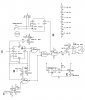
I have been tinkering with this circuit for awhile and would like any and all advice on it. It is for an electic dead bolt lock. U is from a reciever to lock and unlock. SW1 is the door position. B and C are photo transistors for the position of the lock. E is a low voltage circuit. Like I said before any and ALL advice is greatly appreciated. Thanks again for all your help.
 

Attachments

  • door 4.jpg
    door 4.jpg
    154.8 KB · Views: 172
You have 74HCxx ICs with a 9V supply. But their max allowed voltage is 7V and they are spec'd up to only 6V.

You have an LED without a current-limiting resistor so it and/or the 2N3906 driver transistor will burn abd die.
 
If you want to stick with the 9V supply you can considder the 4013 for the flip flops and the 4093 for you NAND ports

they have no problem with the 9V

Robert-Jan
 
Or he can use the 74C00 and 74C74, while more expensive, also work up to 15V. I would go for the 4000 series chips myself.
audioguru said:
You have an LED without a current-limiting resistor so it and/or the 2N3906 driver transistor will burn and die
.
The LED is a flashing LED and doesn't need a resistor.
 
Last edited:
audioguru. I believe 08l36bid doesn't need a current limiting resistor. I am not 100% sure with a PNP though. Thank you.

rjvh. Thank you. I am now not sure if this is what I will stick with.
I'm thinking of using stepper motor instead.
 
I have CD4013BE and 4011BE, but believe they are the wrong family.
 
the difrence between the 4011 and the 4093 is that the 4093 is a smith trigger NAND port it has set triger levels for geting high and low

I don't see an iseu of using the 4011 in this schematic

Robert-Jan

Family is fine CD4013BE and CD4011BE can be used
 
Last edited:
Thank you rjvh. I do not think a smitch trigger is what I want; as battery level falls won't the trigger level fall as well with 4011?
 
I have CD4013BE and 4011BE, but believe they are the wrong family.
They will work OK except that the pinouts are different and the Set & Reset on the 4013 is active high vs active low on the 74HC74. You'll have to change R7&R8 to pulldowns and connect the common of SW1 to the 9V supply instead of ground. I would also add a 10K resistor to the collector of Q1 to limit the base current into Q3.
b_reagle said:
I do not think a smitch trigger is what I want; as battery level falls won't the trigger level fall as well with 4011?
The "trigger level" will change with supply voltage using either the 4011, 4093 or 74C00. If you want a fixed trigger level, use a TL750L05 (Or other LDO regulator) to power the circuit from 5V. You'll have to change Q6 to a logic level FET and U3 (Connected after the TL750L05) so that it triggers at apx 4.5V.
 
Last edited:
Is there any reason not to just lower the battery voltage? Or make a voltage tap on the batteries?
 
But not Q4?
No need there because the base current into Q4 is already limited by R2.
Mikebits said:
Is there any reason not to just lower the battery voltage? Or make a voltage tap on the batteries?
I think the motor is 9V, but then you could also use a lower voltage motor. But that may draw too much current and a regulator will keep some of the motor noise out of the digital circuitry.
 
Is there any reason not to just lower the battery voltage? Or make a voltage tap on the batteries?

The (right)chips and everything else should be good until at least 10vdc, even more. I was thinking maybe 4 AA(6vdc) depends on the motor(still debating). I have one of the kids rc cars ripped apart for right now. The very important part is low voltage. I want to get back in...
 
Why not just run the motor at 9vdc and tap off 6v from the batts for the circuits?
 
Status
Not open for further replies.

Latest threads

Back
Top